
1. What counts as an “accessory” for a corner LED channel system?

A corner LED channel is a system, not just an aluminum extrusion. The “accessories” are everything that completes the mechanical, optical, and protective job.
Typical accessory set:
- Diffuser/lens (opal, clear, prismatic, black “smoke”, frosted)
- End caps (open or closed, often with cable exit)
- Mounting clips, brackets, or adjustable hinges
- Corner joiners and straight joiners (for continuous runs)
- Trim rings or finishing covers (on some architectural profiles)
- Fasteners and adhesive options (screws, VHB tape, magnets)
One common issue is mixing parts across profile families. Two “similar-looking” channels can have different inner widths, lens locking features, or cap geometry. In a retail shelf project, that mismatch can force on-site sanding or tape “hacks.” On a hotel cove, it can show as a visible gap at the corner. In a refrigerated display, it can create a moisture path.
Why this matters to your bottom line: accessories control labor minutes. Correct clip spacing and caps that seat cleanly can save significant time across a multi-room rollout.
| Accessory item | Mechanical role | Optical role | Typical failure if mismatched |
|---|---|---|---|
| Diffuser/lens | Locks into channel | Controls glare/dotting | Lens pops out, cracks, yellowing |
| End cap | Protects edges, cable exit | Blocks light leak | Rattling, visible gaps |
| Mounting clip/bracket | Fixes position and angle | Holds aiming | Sagging, twist, stress |
| Joiner | Aligns two profiles | Reduces seam visibility | Misalignment, lens discontinuity |
2. How do diffusers change glare, dotting, and beam control in corner installs?
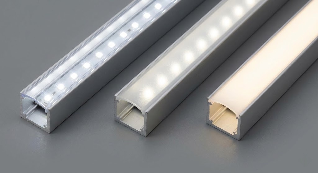
The diffuser is the most visible accessory. It also changes the lighting result more than many people expect.
Three performance outcomes matter in corners:
1) Glare control: Corners often place the light source in a direct line of sight, especially under cabinets or in corridors.
2) Dotting control: LED pitch plus lens distance creates visible “hotspots.” Corners make this worse because your eye naturally tracks along edges.
3) Beam spread: A corner channel can act like an asymmetric luminaire. Lens shape and finish affect where light lands.
In testing, typical lumen loss ranges of 8%–35% depending on diffuser type and thickness. That loss can be acceptable if it buys better visual comfort and fewer complaints.
Field examples:
- Luxury kitchen under-cabinet: clear lens created hard glare on glossy backsplash. Switching to opal reduced glare, and the perceived “quality” jumped.
- Office corridor corner wash: prismatic lens pushed more light forward and reduced wall streaking.
- Retail shelf lips: a thin frosted lens hid dots on 60 LEDs/m strips but still kept good punch on products.
| Diffuser finish | Glare control | Dot hiding | Typical light loss | Best fit examples |
|---|---|---|---|---|
| Clear | Low | Low | 8%–15% | Accent lines where LEDs aren’t visible |
| Frosted | Medium | Medium | 15%–25% | Shelving, cabinet corners |
| Opal (milky) | High | High | 20%–35% | Hospitality, corridors, close viewing |
| Prismatic | Medium-High | Medium | 12%–22% | Forward throw, aisle lighting |
3. Which diffuser materials and profiles fit real jobsite abuse?
Diffuser “material” is not just a datasheet line. It drives scratch resistance, UV stability, and how the lens behaves during install.
Common materials:
- PMMA (acrylic): clear optics and better UV stability, but can crack if forced into a tight channel.
- PC (polycarbonate): higher impact resistance, better for vandal risk, but can yellow faster in harsh UV unless stabilized.
- Silicone lenses (on some flexible systems): great sealing and dot hiding, but can attract dust and oil if not matched to the environment.
Three jobsite scenarios:
- Tile corners in bathrooms: choose a lens that can be removed without prying against ceramic edges.
- Public lobby corners: higher impact risk, so PC often wins.
- Outdoor soffit corners: UV exposure makes stabilized acrylic a safer bet.
| Lens material | Impact resistance | UV behavior | Cleaning resistance | Notes |
|---|---|---|---|---|
| PMMA (acrylic) | Medium | Better | Better | Watch for cracking if forced |
| PC | High | Depends on grade | Medium | Good for public areas |
| Silicone | High (flex) | Good | Medium-Low | Great sealing, dust can stick |
Pro Tip from the VST Technical Team: “If installers need to remove and re-fit the lens during commissioning, pick a lens with a forgiving locking lip. A ‘tight’ lens saves nothing if it costs two cracked pieces per site.”
4. How do covers, end caps, and joiners affect protection and finishing quality?
Covers and caps look minor until they are missing. Then every flaw becomes visible.
End caps come in two main types:
- Closed caps: block light spill and protect the end from knocks.
- Cable-exit caps: allow a clean wire exit with strain relief.
Joiners matter for long runs. A joiner that aligns the aluminum body but ignores the lens seam can still leave a visible “step” in output. For architectural corners in public spaces, that seam can trigger rework even if the electrical side is perfect.
Protection topics that link directly to callbacks:
- Dust: open ends collect dirt that shows up as dark shadows.
- Moisture: in kitchens or bathrooms, vapor migrates into the channel, then condenses.
- Mechanical snagging: unprotected ends can catch cloths or packaging, pulling lenses loose.
| Part type | What it solves | What to check before ordering | Common mistake |
|---|---|---|---|
| Closed end cap | Finish, dust block | Color match, fit tolerance | Cap sits proud, visible gap |
| Cable-exit end cap | Strain relief, neat wiring | Exit hole size, grommet | Wire pinched, insulation damage |
| Straight joiner | Alignment | Screw positions, length | Lens seam misaligned |
| Corner joiner | Clean corner | Angle tolerance | Corner gap that catches the eye |
5. What mounting options work best for corner LED channels?
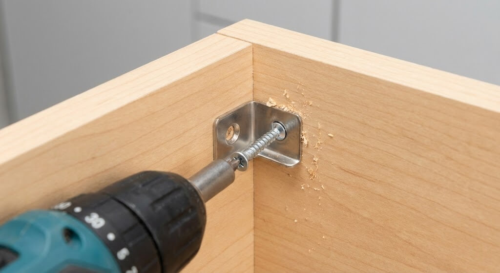
Mounting is where theory meets site reality. In corners, you’re fighting three things: imperfect 90° angles, uneven substrates, and cable routing.
Common mounting methods:
- Screw-fixed clips (spring clips): fast for service access, stable.
- Direct screw-through profile: strong, but can distort thin profiles if over-tightened.
- Adhesive tape (VHB-grade): clean look, no drilling, but surface prep must be disciplined.
- Magnetic mounts: great for steel racks and serviceable fixtures.
- Adjustable brackets: help when corners are not truly square.
Tape-only installs on painted drywall corners are a frequent failure point. Paint film can peel under load or heat, and the whole run drops.
Three use cases:
- Office partitions: clips allow quick removal during tenant changes.
- Metal display gondolas: magnets reduce drilling time and keep things serviceable.
- Stone or tile corners: brackets avoid drilling into finished surfaces.
| Mounting method | Speed | Serviceability | Best substrate | Risk |
|---|---|---|---|---|
| Clips | Fast | High | Wood, drywall studs, aluminum | Clip spacing too wide = sag |
| Screw-through | Medium | Medium | Timber, metal | Profile twist from over-tightening |
| VHB tape | Fast | Low-Medium | Clean metal, glass | Paint peel, adhesion loss |
| Magnet | Fast | High | Steel | Pull strength mismatch |
| Adjustable bracket | Medium | High | Mixed/uneven corners | More parts, more planning |
6. How do you choose mounting for drywall, tile, aluminum, and wood corners?
Substrate selection is where many projects get “surprises.” A corner profile that feels rigid on a bench can flex on a wall if the substrate is soft.
Drywall corners:
- Aim to anchor into studs or add backing. If you can’t, use multiple clips and spread load.
- Avoid relying on paint adhesion. Tape sticks to paint, not to drywall.
Tile corners:
- Use brackets that sit on grout lines where possible.
- If drilling is unavoidable, plan hole placement and use proper tile bits. A cracked tile is a budget problem and a schedule problem.
Aluminum corners (frames, extrusions):
- Self-tapping screws work, but watch for galvanic issues if mixing metals in wet zones.
- Tape performs well on clean, degreased aluminum.
Wood corners:
- Screws and clips are simple. The bigger issue is seasonal movement, which can open small gaps at lens seams.
The cleanest installs happen when the mounting plan is decided before the channel length is cut. That allows cable exits and cap types to match.
| Substrate | Preferred mount | Prep step | What goes wrong in the field |
|---|---|---|---|
| Drywall | Clips into stud | Find stud lines | Sagging from hollow anchors |
| Tile | Brackets or adhesive | Clean grout line | Cracked tile, uneven corner |
| Aluminum | Tape or screws | Degrease | Tape fails from oil residue |
| Wood | Clips or screws | Pilot holes | Warping opens visible seams |
7. How do corner angles and lens geometry change the light on the wall?
Corner channels are sold as “45° corner profiles” most of the time, but the real output depends on angle, LED position, and lens geometry.
Angle and aiming:
- A 45° profile can split light between two surfaces. Great for cove corners and cabinet corners.
- A 60° or asymmetric profile can push light more onto one surface, which helps for wall-wash effects.
- A 90° corner profile often acts more like a line light with less wall wash.
Lens geometry:
- Flat lens tends to keep the beam closer to the channel axis.
- Domed lens can soften the edge and reduce dotting at low mounting heights.
- Prismatic lens can redirect light forward, which is useful when the corner is high and you need throw.
Three examples:
- Hotel corridor upper corners: 45° profile with opal lens gave a soft “floating” line with low glare.
- Retail ceiling corner: prismatic lens reduced dark zone on the product wall.
- Stairwell corners: asymmetric profile pushed light onto treads without lighting the opposite wall too brightly.
| Vs. option | Visual effect | Where it fits | Trade-off |
|---|---|---|---|
| 45° vs 90° corner | More wall/ceiling wash vs more direct line | Cove edges vs sharp architectural lines | 45° can show glare if lens is clear |
| Flat lens vs domed lens | Sharper edge vs softer blend | Modern lines vs hospitality | Domed can reduce peak intensity |
| Opal vs prismatic lens | Softer look vs more forward throw | Close viewing vs higher mounting | Prismatic can show texture up close |
8. How do wiring, end-cap exits, and service access affect install time?
Corners compress space. That means wiring decisions become mechanical decisions.
Three practical rules:
- Plan cable exit direction before cutting the profile. A wrong-side exit can force a visible cable loop.
- Use strain relief at the cap. A tight bend at the exit point can break conductors over time.
- Keep service access in mind. If the driver is hidden above a ceiling, make sure the corner run can be removed without ripping finishes.
A corner run often has two long legs. If you feed only one end, the far corner can look dim, especially on higher-current strips.
Three wiring layouts that work:
- Center feed with two equal legs for uniformity.
- Dual-end feed for long runs where drivers allow.
- Hidden junction box at the corner with short pigtails.
| Wiring choice | Best scenario | What it saves | What it can cost if wrong |
|---|---|---|---|
| Center feed | Two similar leg lengths | Better uniformity | Extra routing at corner |
| Dual-end feed | Long runs, high current | Lower voltage drop | More wiring time |
| Corner junction | Tight cabinetry | Clean look | Harder service if buried |
9. Common Myth: “Any diffuser will hide LED dots in a corner.” Reality: spacing, lens height, and strip type matter.
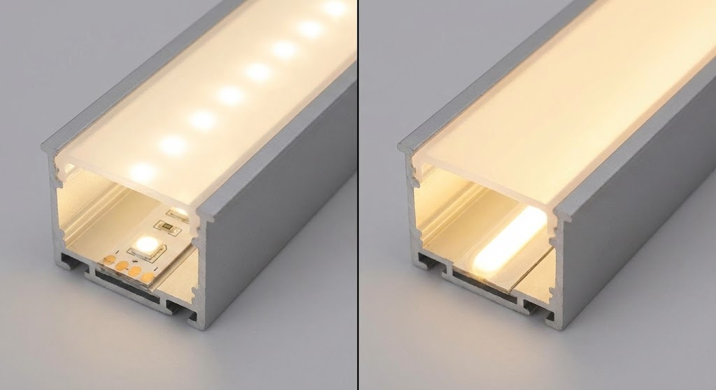
This myth causes a lot of disappointment. People swap lenses and expect miracles, but dotting is geometry.
Reality check:
- LED pitch matters: 60 LEDs/m behaves very differently from 120 LEDs/m.
- Lens height matters: the distance from LED to diffuser affects blending.
- Strip type matters: COB strips have near-continuous phosphor, while SMD strips show individual emitters.
When we tested this against a standard 12V strip at 60 LEDs/m in a shallow corner channel, even an opal lens still showed faint spotting at close view. Switching to a higher-density strip reduced dotting more than any lens swap.
Three practical examples:
- Jewelry display: customer wanted “no dots” at 20 cm view distance. The fix was COB strip plus shallow opal lens.
- Office corner accent: viewer distance was 2–3 meters, so frosted lens on SMD was fine and kept higher brightness.
- Restaurant ceiling coves: using a deeper channel with a domed lens hid dots without heavy lumen loss.
If you ignore this, you risk reputation damage. The client sees dots, assumes low quality, and your margin erodes under rework.
| Factor | What you see in the corner | Better fix than “just change lens” |
|---|---|---|
| Low LED density | Strong hotspots | Higher density or COB strip |
| Shallow channel | Poor mixing | Deeper profile or domed lens |
| Clear lens | Sharp dots and glare | Frosted/opal or prismatic lens |
| Very close viewing | Every flaw visible | Combine deeper channel + COB |
10. What checklist prevents cracked lenses, sagging corners, and early failures?
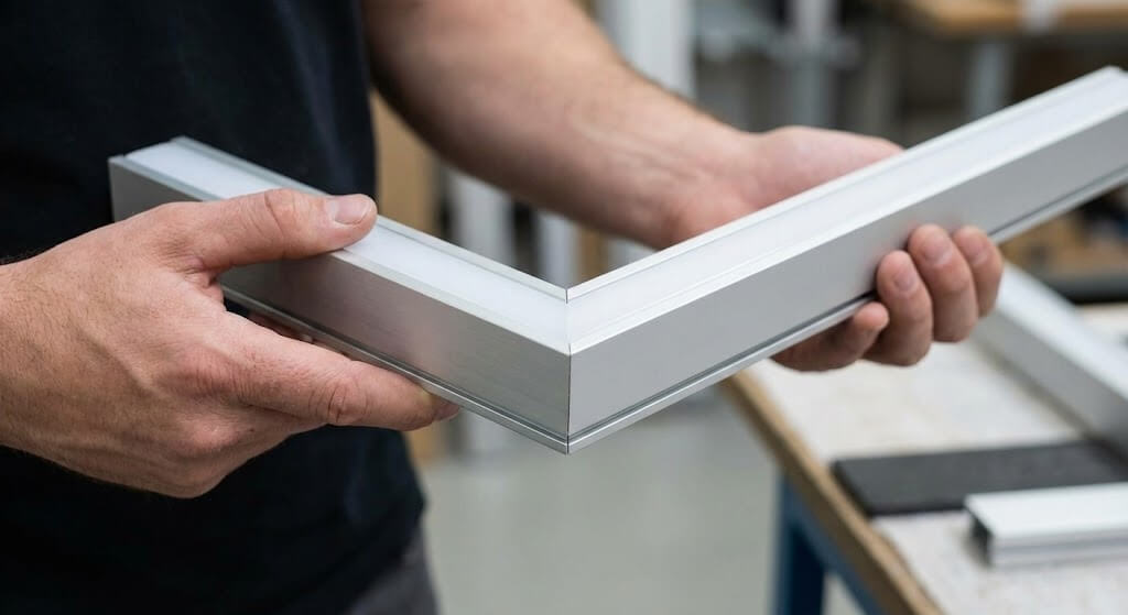
Most corner channel failures are mechanical. The electrical parts get blamed, but the root cause is often stress, poor prep, or bad clip spacing.
Here’s what we see repeatedly:
- Lenses crack because the channel is twisted into a non-square corner.
- Corners sag because clips are spaced too far or only tape is used on paint.
- Light leaks at ends because caps are not seated or the channel is cut out of square.
Use this simple process on site:
- Dry-fit the channel and lens before peeling tape or fixing clips.
- Confirm the corner angle with a small square. Real corners can be 87° or 93°.
- Decide cable exits and cap types before final mounting.
- If you need a continuous look, align lens seams and joiners, not only aluminum seams.
Rush schedules make “skip the dry-fit” tempting. It saves minutes and can cost hours later.
| Checklist item | What to check | Fast test | If it fails |
|---|---|---|---|
| Corner angle fit | Channel sits flat | Hold in place, no force | Use adjustable bracket or shim |
| Clip spacing | No bowing | Press mid-span | Add clips, shorten span |
| Tape prep | Surface is clean | Alcohol wipe, no residue | Re-clean, change to clips |
| Lens insertion | Smooth snap-in | Slide along run | Fix twist, re-cut end |
| End cap seating | No gap/light leak | Lights off, look for spill | Re-seat cap, check cut square |
Conclusion
Corner LED channel accessories decide how the job looks, how fast it installs, and how many callbacks you get. Pick the diffuser based on glare, dotting, and viewing distance. Match covers, caps, and joiners to the profile so seams stay clean and ends stay protected. Choose mounting hardware that fits the substrate, not just what’s fast on paper. If you’re unsure about lens choice or voltage drop on a two-leg corner run, send our engineering team your drawing and target CCT. We’ll review the stack-up and point out risks before you cut anything.
FAQ
Q1: What are corner LED channel accessories?
Corner LED channel accessories are the lenses/diffusers, end caps, joiners, and mounting parts that complete a corner profile mechanically and visually. They control glare and dotting, protect the ends and wiring, and set the channel angle so it stays straight over time.
Q2: How do diffusers affect light output and glare?
A diffuser reduces glare and helps hide LED hotspots, but it also reduces light output. Clear lenses tend to keep higher lumens with more glare and visible dots, while opal or frosted lenses reduce discomfort and smooth the line at the cost of more lumen loss.
Q3: Which mounting method is best for corner LED channels?
Clips and brackets are the safest default for most sites because they keep the profile serviceable and resist sag. Tape works well on clean metal or glass, but it’s risky on painted drywall corners unless you have solid prep and light weight.
Q4: Do end caps and joiners change IP protection?
Yes. Even with an IP-rated strip, open ends and poorly seated caps let dust and moisture into the channel. Cable exits without strain relief can also pull the cap out slightly, creating a leak path and visible light spill.
Q5: How can I stop LED dots from showing through the diffuser?
Start with geometry: higher-density or COB strips, deeper channels, and lenses that provide more mixing distance. Opal lenses help, but they can’t fully fix a shallow channel with wide LED pitch viewed from close range.
