
Installing a plaster-in LED profile means recessing a trimless aluminum channel into a wall or ceiling so the profile sits flush and the light line looks clean after plastering and painting.
The process depends on accurate framing, correct profile fixing, careful plaster build-up, and proper LED strip and diffuser installation after finishing work. If any of those steps go wrong, you get cracks, shadow lines, overheating, or visible uneven edges.
If you are planning a trimless linear lighting job, that risk is real. A poor install can lead to callbacks, rework, and unhappy clients who notice every uneven joint once the light is switched on. The good news is that the method is straightforward when you follow the right sequence.
In our lab tests using integrating spheres and thermal checks on aluminum housings, we have seen that proper profile selection and mounting affect not only appearance but also strip temperature and long-term lumen stability.
This article explains how to install plaster in LED profile step by step, with practical site advice, tables, and common failure fixes.
1. What is a plaster-in LED profile and where is it used?
A plaster-in LED profile, sometimes called a trimless LED profile or mud-in LED channel, is an aluminum extrusion designed with perforated or winged edges that sit under plaster or drywall compound. Once finished, the visible result is a narrow recessed light opening without a bulky trim.

We often see installers struggle with the difference between a standard recessed channel and a plaster-in version. A regular recessed profile usually has a visible flange. A plaster-in profile disappears into the surface. That is why it is common in higher-end interiors where visual cleanliness matters.
Typical applications include:
- Gypsum board ceilings in offices
- Hotel corridors with linear guidance lighting
- Residential living rooms with trimless ceiling lines
- Wall washing features in galleries
- Joinery integrations in custom furniture
From our manufacturing floor perspective, the profile design matters because plaster-in channels need stronger edge geometry to resist cracking around the opening.
| Application Area | Why Plaster-In Profile Is Used | Main Site Concern |
|---|---|---|
| Ceiling linear light | Clean trimless finish | Alignment over long runs |
| Wall niche lighting | Hidden architectural effect | Crack control |
| Corridor lighting | Continuous modern look | Joint consistency |
| Retail shelving | Minimal visible hardware | Heat dissipation |
2. How do you choose the right plaster-in LED profile?
Not every profile is suitable for every project. You need to match the housing to board thickness, strip wattage, light output target, and installation location.
Here is the deal: selecting the wrong profile creates problems before installation even starts.
Key selection points include:
- Board or plaster thickness
- Profile width and depth
- LED strip width
- Heat dissipation capacity
- Diffuser type
- Mounting method
- Indoor or damp-area use
In a hotel ceiling, a shallow profile may fit the cavity but may not hide LED dots. In a luxury retail shelf, a narrow opening may look elegant but may restrict airflow. In a long corridor, a weak profile can drift out of line and show every imperfection after painting.
Common Myth: a deeper profile is always better. Reality: depth helps reduce spotting, but if it does not match strip beam angle, diffuser quality, and cavity space, it may complicate the install without improving the visual result.
| Selection Factor | What to Check | Why It Matters |
|---|---|---|
| Profile depth | 10mm, 15mm, 20mm+ | Affects dot visibility |
| Internal width | Match strip PCB width | Avoids strip lifting |
| Aluminum mass | Thick vs thin body | Affects cooling |
| Edge type | Perforated wing or mesh edge | Better plaster bonding |
| Diffuser finish | Opal, frosted, clear | Changes output and appearance |
When comparing options, also account for installation tolerance — some profiles include adjustable brackets or shims that make in-situ alignment easier. For wet rooms or areas with high humidity, choose profiles and diffusers rated for those environments and ensure any gasket or seal is specified by the manufacturer.
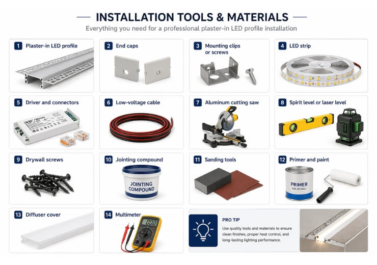
3. What tools and materials are needed before installation starts?
Preparation saves time on site. If the crew starts cutting boards before confirming cavity depth, feed cable position, and profile length, errors accumulate fast. We once saw a project fail because the electrician placed the cable outlet 40 mm off center across eight ceiling runs. The profiles had to be reopened and patched.
You usually need:
- Plaster-in LED profile lengths
- End caps if required
- Mounting clips or screws
- LED strip
- Driver and connectors
- Low-voltage cable
- Aluminum cutting saw or fine blade miter saw
- Spirit level or laser level
- Drywall screws
- Jointing compound or plaster
- Sanding tools
- Primer and paint
- Diffuser cover
- Multimeter
What’s the real story?
The profile is only one part of the system. Driver access, serviceability, and strip replacement matter too. Our Chief Engineer notes that heat dissipation is often ignored in early planning, yet it directly affects maintenance cost and lumen depreciation.
| Item | Purpose | Common Mistake |
|---|---|---|
| Laser level | Straight alignment | Relying on visual alignment |
| Multimeter | Voltage check | Skipping polarity check |
| Fine tooth saw | Clean profile cuts | Rough cuts damaging diffuser fit |
| Joint compound | Flush finish | Applying too thick in one pass |
| Driver | Power supply | Hiding driver with no access |
Also bring small consumables: painter’s tape for masking, rags for cleaning swarf, and replacement connectors. Label each strip and driver during staging so that if multiple batches are on site you avoid color bin mixing at joints.
4. How should the site be prepared before fixing the profile?
Site preparation determines whether the finished light line looks crisp or amateur. Before fixing the profile, check substrate flatness, framing spacing, cable routing, and driver location. If this stage is rushed, plaster cracking and uneven reveals become much more likely.
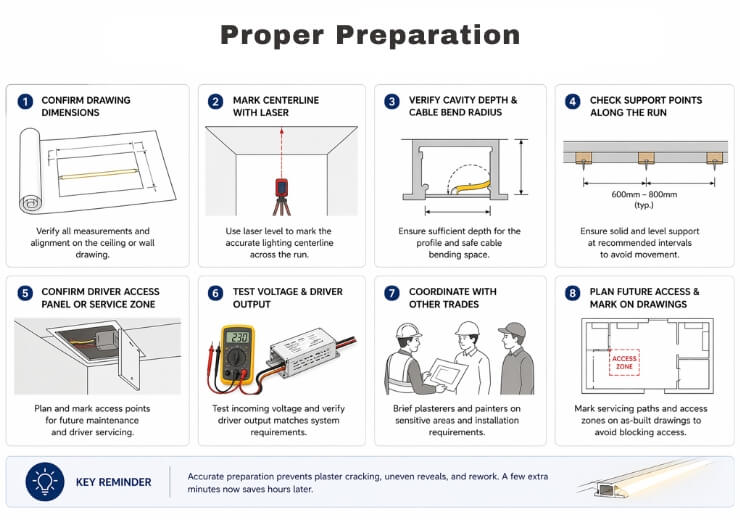
A good pre-install checklist includes:
- Confirm ceiling or wall drawing dimensions
- Mark the lighting centerline with laser reference
- Verify cavity depth against profile depth and cable bend radius
- Check support points along the run
- Confirm driver access panel or service zone
- Test incoming voltage and driver output
In our lab tests using integrating spheres, light quality is often judged after installation, but field appearance starts much earlier with mechanical accuracy. A straight LED line on paper still looks poor if the profile twists by even a few millimeters across a long run.
We often see installers struggle with unsupported mid-spans. On a 2-meter to 3-meter run, that can create movement during plastering. Later, fine cracks appear at the profile edge.
| Site Check | Target | Risk If Ignored |
|---|---|---|
| Surface flatness | Even substrate | Wavy light line |
| Framing support | Regular fixing points | Profile movement |
| Cable route | Centered and protected | Strip connection stress |
| Driver access | Serviceable location | Expensive rework |
| Moisture condition | Dry install area | Weak plaster bond |
Also coordinate with other trades. Plasterers and painters should be briefed on sensitive areas. If servicing paths need to be planned for future access, mark them clearly on the as-built drawings so wall finishes are not accidentally made inaccessible.
5. How do you fix the plaster-in LED profile into drywall or plasterboard?
Once the site is ready, fix the profile securely and keep it perfectly straight. This is where it gets interesting. Many visible finish defects are not plaster issues at all. They start with poor mechanical fixing.
Typical method:
- Cut the profile to length with clean square ends.
- Dry-fit the profile into the opening.
- Mark fixing points at regular intervals.
- Fix to framing, board edge, or brackets depending on the design.
- Recheck level and straightness.
- Protect the profile channel during plastering.
For ceiling runs, using a laser is better than relying on the board seam. For wall runs, watch for bowing caused by uneven stud faces. We once saw three parallel light lines in a showroom where the center run dipped by 5 mm. Under switched-on light, the defect was obvious.

Below is a useful comparison for power system planning around profile runs.
| Factor | 12V LED Strip | 24V LED Strip |
|---|---|---|
| Voltage drop over long runs | Higher | Lower |
| Typical run suitability | Shorter lengths | Longer lengths |
| Current draw | Higher | Lower |
| Site wiring flexibility | More limited | Better for linear runs |
| Common use with plaster-in profile | Small features | Ceiling and corridor lines |
When we tested this against a standard 12V strip on longer profile runs, voltage loss caused visible brightness reduction near the far end. That matters because clients read it as bad workmanship, even if the wall finish is perfect.
6. How do you plaster around the LED profile without cracks or uneven edges?
This is the stage most people worry about, and for good reason. The goal is to bond the plaster or joint compound to the perforated wings, feather it into the board, and keep the light aperture clean and sharp.
A sound method looks like this:
- Apply the base coat in thin layers
- Press compound through perforations or mesh areas
- Feather outward beyond the profile edge
- Allow full drying between coats
- Sand lightly, not aggressively
- Prime before final paint
But there’s a catch. Thick compound in one pass often shrinks and cracks. We often see installers struggle with overfilling the channel edge and then sanding too close to the opening, which rounds the detail and ruins the trimless effect.
Three common site examples stand out. In office ceilings, poor drying control causes hairline cracks. In villas, painters sometimes fill the profile lip with paint, making diffuser insertion difficult. In commercial corridors, long continuous runs reveal tiny edge waves once grazing light hits the surface.
| Plastering Issue | Likely Cause | Fix |
|---|---|---|
| Hairline crack at edge | Thick coat or movement | Re-tape, refill in thin coats |
| Rounded opening | Over-sanding | Rebuild edge carefully |
| Compound inside channel | Poor masking | Clean before curing |
| Uneven line | Profile not fixed straight | Reopen and reset section |
| Poor bond | Dust or wet surface | Clean and dry substrate |
A few practical tips: always use a mechanical stop when sanding near the reveal to avoid accidental rounding, and consider a narrow protective strip of painter’s tape across the channel edge which can be removed when the final coat is dry.
For plaster mixes, add a small amount of acrylic binder to reduce shrinkage on tricky substrates but only if compatible with the manufacturer’s guidance.
7. When should the LED strip, diffuser, and driver be installed?
In most projects, the aluminum profile goes in during board and plaster work, while the LED strip and diffuser go in after sanding, priming, and painting are complete. That sequence reduces contamination and protects the lighting components.
Recommended order:
- Install and fix profile
- Complete plastering and sanding
- Prime and paint the surrounding surface
- Clean the channel fully
- Test driver voltage and polarity
- Install LED strip
- Test light output
- Fit diffuser and end caps
From our manufacturing floor perspective, this order supports cleaner thermal contact between strip adhesive and aluminum. Dust under the strip weakens adhesion and reduces heat transfer. That is not a minor issue. In our thermal imaging checks, poorly bonded strips can run several degrees hotter, especially with 12W/m to 20W/m products.
Pro Tip from the VST Technical Team: always dry-fit the diffuser after plastering and before final strip installation. If the profile opening was distorted during finishing, you want to fix that before the LED strip goes in.
| Installation Stage | Do Now or Later? | Reason |
|---|---|---|
| Profile fixing | Now | Needed before plaster |
| Driver rough wiring | Now | Hidden infrastructure |
| Final strip install | Later | Avoid damage and dust |
| Diffuser fitting | Later | Protect finish and lens |
| Final testing | Later | Verify completed system |
Also label access points and test multiple strips at once for color consistency before finalizing the join. Record test results and photograph the installation for the client handover pack to reduce disputes later.
8. How do you handle corners, long runs, and continuous lines?
Straight short runs are manageable. Long runs, corner transitions, and seamless lines are where workmanship gets tested. Ready for the good part? Most failures on architectural linear lighting happen in these details, not in the middle of a simple 1-meter profile.
For long runs:
- Align joints on a common reference line
- Use mechanical support close to every joint
- Check for thermal expansion allowance
- Keep strip feed planning consistent
For internal and external corners:
- Decide between miter cut and corner connector
- Keep diffuser transitions neat
- Test light continuity before closing access
For continuous designs in a hotel corridor, you may need multiple power feeds. For a retail wall, a single visible misalignment at a 90-degree corner can undermine the whole feature. For custom millwork, corner movement from timber expansion can stress the profile edges.
We once saw a project fail because the profile joints were mechanically aligned but the LED strips came from different bins, creating a slight color shift at the connection point. We explain this because ignoring consistency causes reputation damage on premium jobs.
| Detail Type | Best Practice | Main Risk |
|---|---|---|
| Long straight run | Laser alignment and extra supports | Sagging line |
| Internal corner | Accurate miter cut | Visible gap |
| External corner | Reinforced fixing | Edge cracking |
| Multi-run corridor | Same batch strips | Color mismatch |
Also allow for discreet access panels at intervals for continuous runs to permit future maintenance without disturbing large areas of finish. When joining runs, stagger joints where possible so any minor misalignment is less noticeable.
9. What safety, thermal, and maintenance issues should you check?
A plaster-in LED profile is not only an architectural detail. It is also part of an electrical and thermal system. If heat, access, and wiring are ignored, the sleek finish becomes a maintenance problem.
Check these points:
- Driver wattage headroom
- Profile thermal mass versus strip wattage
- Correct polarity and cable sizing
- Ventilation in enclosed cavities
- Access to driver replacement point
- Certification requirements for the market
In our lab tests using integrating spheres, we have seen luminous output fall faster when strips run hot over time.

In thermal imaging, undersized profiles paired with high-density strips show clear hotspot patterns. In one hospitality project, a concealed driver without access turned a simple replacement into ceiling repair work.
This matters to your bottom line. One failed inaccessible driver can wipe out the margin on a small installation because labor, patching, and repainting cost more than the component itself.
| Checkpoint | Recommended Practice | Business Impact |
|---|---|---|
| Driver loading | Keep margin below max load | Longer life |
| Heat dissipation | Match profile to wattage | Fewer failures |
| Cable size | Limit voltage drop | Uniform brightness |
| Service access | Provide reachable driver point | Lower maintenance cost |
| Compliance | Use certified components | Lower liability |
Include a basic maintenance schedule in the project handover: periodic visual checks, a run-time test every 6–12 months, and a prompt replacement plan for drivers reaching end-of-life. Photographic records of the installation and wiring paths will save time if re-entry is required.
10. How do you test, inspect, and troubleshoot the finished installation?
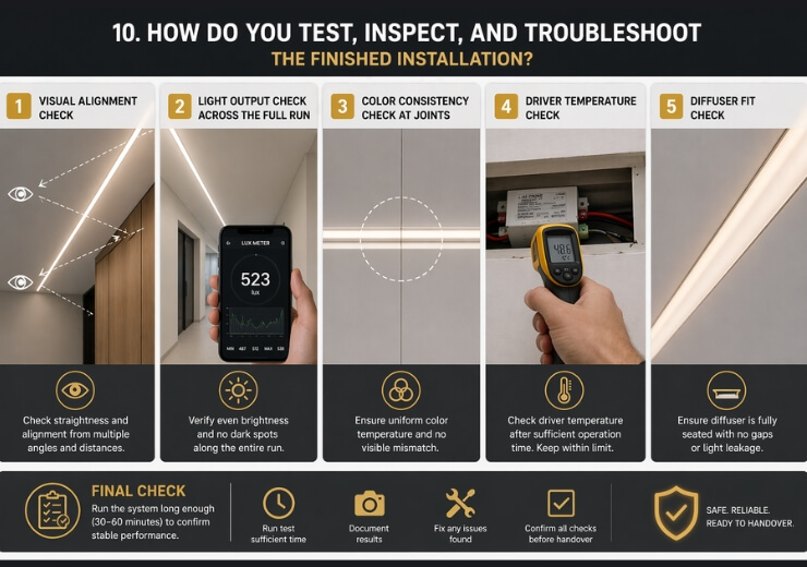
Before handover, test the system under real operating conditions. Don’t just power it on for ten seconds. Run it long enough to see thermal behavior, brightness consistency, and finish quality under working light.
Your final inspection should include:
- Visual alignment check from multiple angles
- Light output check across the full run
- Color consistency check at joints
- Driver temperature check
- Diffuser fit check
- Surface crack inspection after curing
Here is a quick reference troubleshooting table.
| Symptom | Possible Cause | Action |
|---|---|---|
| One end dimmer | Voltage drop | Add power feed or use 24V layout |
| Visible LED dots | Shallow profile or clear diffuser | Use deeper profile or opal cover |
| Flicker | Driver mismatch or loose wiring | Check compatibility and terminals |
| Edge crack | Movement or thick plaster | Refinish with proper support |
| Diffuser will not fit | Paint or compound buildup | Clean channel and trim excess |
We often see installers struggle with testing too early, before paint fully cures or before load conditions stabilize.
In luxury homes, this leads to rushed snag lists. In offices, it delays handover. In retail spaces, it can affect opening schedules. A disciplined final test protects both quality and schedule.
Conclusion
Knowing how to install plaster in LED profile comes down to sequencing, straight fixing, controlled plastering, and correct electrical planning. If you choose the right profile, prepare the site properly, manage heat, and leave strip installation until the finish is complete, you get a clean trimless result with fewer callbacks.
If you are unsure about run length, wattage, or profile selection for a specific drawing, contact our technical support team with your layout and we can help review the details.
A final practical reminder: always build a short mock-up on site for client approval when the detail is visible in occupied spaces. This reduces expectation gaps and prevents late-stage design changes that are expensive to correct.
FAQ
Q1: What is a plaster-in LED profile?
A plaster-in LED profile is a trimless aluminum channel designed to be recessed into plasterboard or drywall so the light opening remains visible while the profile edges are hidden under plaster or joint compound.
Q2: How does a plaster-in LED profile work?
It works by fixing the aluminum housing into the wall or ceiling structure, bonding its side wings into the plaster layer, and then installing the LED strip inside the recessed channel after finishing work is complete.
Q3: Can you install the LED strip before plastering?
It is usually better not to. Installing the strip after plastering, sanding, and painting keeps dust and moisture away from the LED components and gives better adhesive contact with the aluminum.
Q4: Why do cracks appear around plaster-in LED profiles?
Cracks often come from profile movement, thick plaster coats, poor substrate preparation, or weak bonding between the profile wing and the surrounding finishing material.
Q5: Is 24V better than 12V for long plaster-in profile runs?
For many longer linear runs, yes. A 24V system usually reduces voltage drop, supports better brightness consistency, and gives more flexible feed planning than a comparable 12V setup.
