
led strip lights for train compartment applications are low-profile linear LED systems designed for passenger cabins, sleeper rooms, luggage zones, corridors, and service areas in rail vehicles. The right strip must handle vibration, voltage variation, heat, fire-safety demands, cleaning chemicals, and long daily operating hours without color shift or nuisance failures.
LED Strip Lights for Train Compartment Use is not just a lighting topic. It is a passenger comfort, maintenance cost, and safety topic. A wrong strip can cause flicker, adhesive failure, hot spots, color mismatch, and callbacks across many cars. The practical answer is to specify the strip, driver, profile, diffuser, wiring, and test plan as one system. From our manufacturing floor perspective, train projects need tighter checks than standard indoor decorative lighting because vibration, space limits, and duty cycles are much harsher.
Consider also regulatory compliance early in the project. Railway lighting often must meet EN 45545 or the NFPA 130 standard for fire performance, while electrical components should be selected with EN 50155 and EMC considerations in mind. Early consultation with the vehicle owner (and their maintenance team) on cleaning agents, expected operating hours, and spare-part access will avoid later disputes and change orders.
1. What makes led strip lights for train compartment projects different from normal indoor lighting?
A train compartment is a moving environment. That changes the specification. In an office, a strip faces stable voltage and moderate use. In a coach, the same strip may run 16 hours per day and face frequent vibration and cleaning agents.
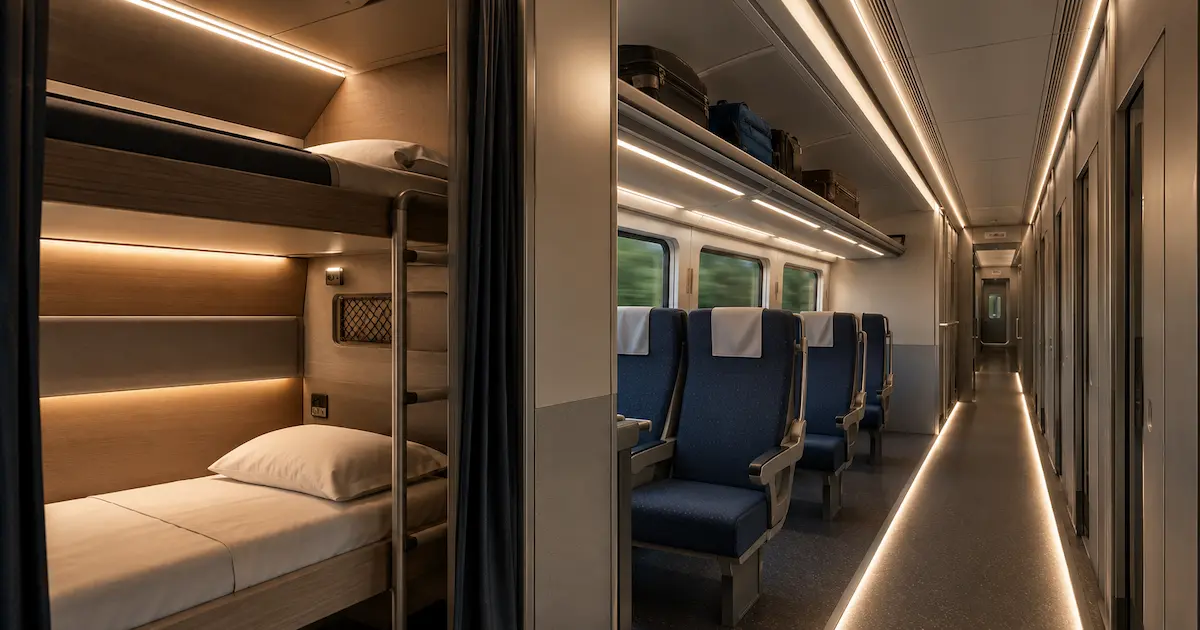
The light must work as part of the vehicle, not as a loose decorative product. A sleeper cabin needs soft, low-glare light; a luggage rack needs clear visibility; a corridor needs reliable guidance lighting without sharp brightness lines.
We often see installers struggle with three field issues: strips peeling from painted metal, voltage drop across long coach runs, and visible LED dots through shallow covers. Each problem creates rework. In one refurbishment, a contractor used standard indoor adhesive tape in berth areas; summer operation caused several sections to detach.
Practical mitigations include mechanical retention in addition to adhesive (clips, riveted brackets), using specified surface-prep chemicals before bond, and designing power feeds so long runs are powered at multiple points to reduce voltage drop. Also, define inspection intervals in the maintenance manual so adhesive and connectors are checked after defined mileage or hours.
| Train compartment zone | Lighting goal | Common risk | Better specification direction |
|---|---|---|---|
| Sleeper cabin | Soft comfort light | Glare near eye level | COB strip or dense SMD with opal diffuser |
| Passenger seat area | Reading and ambient light | Color mismatch | Tight CCT binning and batch control |
| Luggage rack | Clear object visibility | Shadow lines | Higher lumen strip with profile angle control |
| Corridor | Safe movement | Flicker and dark spots | Stable driver, continuous run planning |
| Service panel | Maintenance visibility | Moisture and dirt | Protected strip with easy access design |
2. Which voltage is better for train compartment LED strip lighting?
Voltage choice affects safety, voltage drop, driver layout, and labor, and the same basic principles used when selecting 12V and 24V LED strips for vehicles also apply to many train-compartment lighting circuits. For train compartment projects, 24V is often preferred over 12V for medium and long runs because it reduces current and voltage drop. Short reading lights and compact modules can still use 12V.
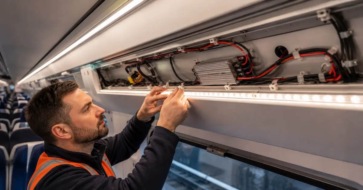
Many rail vehicles use onboard DC systems (24V, 48V, 72V, 110VDC). The LED strip rarely connects directly to vehicle power; use a proper DC-DC converter or LED driver to manage spikes and noise.
When choosing voltage, set a maximum allowable voltage drop (commonly <3% at end-of-run) and calculate cable cross-section accordingly. Use a voltage-drop calculator or the formula V_drop = I * R_total and plan power injection points for runs that exceed the acceptable drop. Remember that higher vehicle operating temperatures increase conductor resistance and that connectors add contact resistance.
| Item | 12V LED strip | 24V LED strip | 48V system strip |
|---|---|---|---|
| Best use | Short local lights | Medium cabin runs | Long linear runs with special design |
| Voltage drop | Higher | Lower | Lowest among these options |
| Cutting interval | Shorter | Medium | Longer, depends on circuit |
| Driver choice | Very common | Very common | More project-specific |
| Train fit | Small berth and task zones | Most cabin linear lighting | Long continuous architectural lines |
Pro Tip: “Calculate current, cable length, ambient temperature, and allowable end-of-run brightness loss.” Also plan for inrush and transient conditions by verifying the converter’s transient protection and by fitting transient voltage suppressors where the power feed is exposed to switching spikes.
3. How should brightness and wattage be specified for train compartments?
Lumen efficiency, diffuser loss, mounting height, and surface reflectance decide usable light. Excess wattage creates heat that shortens LED life and stresses adhesive. The right target is adequate lux at passenger level with stable thermal behavior.
Many cabin ambient schemes use 4.8–12W/m depending on diffuser loss and layout. Reading or luggage lighting needs higher localized output. Test samples inside the real profile to verify results after thermal stabilization.
Specify photometric targets (lux at a reference plane) rather than relying solely on watts per metre. Ask suppliers to provide lumen output at the maximum expected operating temperature and after a 1-hour thermal stabilization period. Where possible, request L70 or L90 lifetime projections under the specified mounting conditions (for example L70@50,000 hours when fitted inside an aluminum profile with the driver located externally).
| Application | Typical wattage range | Suggested CCT | Design note |
|---|---|---|---|
| Sleeper ambient light | 4.8–9.6W/m | 2700K–3500K | Use dimming and low-glare cover |
| Seat area indirect light | 6–12W/m | 3000K–4000K | Check reflections from panels |
| Luggage rack | 9.6–14.4W/m | 3500K–5000K | Aim light toward bags, not eyes |
| Corridor line light | 6–10W/m | 3000K–4000K | Prioritize uniformity |
| Maintenance/service area | 10–18W/m | 4000K–5000K | Protect against dirt and contact |
Design note: include a margin for diffuser loss (typically 10–30% depending on diffuser opacity) when calculating required strip lumens. Run a worst-case thermal test with the diffuser fitted and measure lumen output and temperature at the PCB.
4. Which LED strip type works best: SMD, COB, or rigid linear modules?
Choice depends on viewing distance, profile depth, beam appearance, and service method, while a low-profile LED channel can help fit linear lighting into shallow train ceilings, berth panels, luggage racks, and narrow trim details. SMD strips are efficient and flexible; COB gives a continuous line with fewer dots; rigid modules suit areas needing mechanical stability.
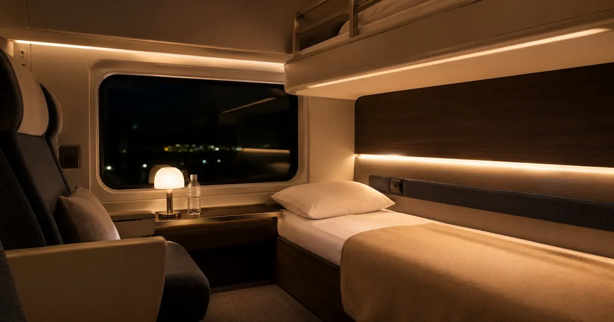
Check PCB thickness, copper weight, solder quality, and LED binning—these often matter more than the marketing label. A thin copper track on a high-watt strip runs hot and shifts color.
COB is increasingly popular for visible lines because it reduces pixelation, and a 12V COB LED strip can be suitable for short berth lights, compact reading areas, seat trim, and other localized train-compartment applications when paired with proper heat sinking. Rigid modules give repeatable optical performance and reliable mounting but add weight and require mechanical fastening points. For retrofit projects, consider modular sections with sealed connectors to simplify replacement and avoid cutting or re-soldering on-site.
| LED format | Strength | Limitation | Suitable train use |
|---|---|---|---|
| SMD 2835 strip | Efficient, flexible | Dots visible with shallow diffuser | Luggage, corridor, indirect cabin light |
| SMD 3528 strip | Low power, gentle | Lower brightness | Soft mood and marker lighting |
| COB strip | Smooth continuous line | Needs good heat path | Visible cabin lines and sleeper areas |
| Rigid linear module | Strong mounting | Less flexible | Ceiling panels and service zones |
| Side-emitting strip | Thin edge light | Lower output choices | Seat trim and narrow grooves |
Practical tip: request a sample assembly using the intended strip, diffuser, and either a shallow profile or deep LED channel, then inspect it for visible dots, hot spots, glare, and color uniformity at the intended viewing distance.
5. What color temperature and CRI should be used inside train compartments?
3000K–4000K is common for passenger areas, and the U.S. Department of Energy’s guidance on LED color characteristics helps explain how color temperature and color rendering influence perceived lighting quality. Warm white suits sleeper cars, while neutral white works well for day coaches and corridors. For premium trains, Ra90+ improves fabric, skin tone, signage, and food appearance. Specify binning (SDCM) and batch marking to avoid visible mismatches.
Also define dim-to-warm behavior if the car requires warm tuning for night modes. For instance, a dim-to-warm strip that drops from 3000K toward 2200K at low levels can improve passenger comfort in overnight services. Specify acceptable visual thresholds, such as maximum delta CCT between adjacent runs and a requirement for batch traceability marking on each reel.
| Parameter | Standard cabin option | Premium cabin option | Why it matters |
|---|---|---|---|
| CCT | 3000K–4000K | Fixed 3000K or 3500K bin | Consistent visual tone |
| CRI | Ra80+ | Ra90+ | Better color appearance |
| Binning | 5-step SDCM | 3-step SDCM | Reduces mismatch risk |
| Dimming range | 10–100% | 1–100% if supported | Night comfort |
Specify acceptable SDCM (e.g., 3-step on premium projects) and require supplier batch labeling so any mixed reels are obvious during installation.
6. How do heat dissipation and aluminum profiles affect service life?
Heat is a common failure driver, and understanding the correct solution to LED strip heat issues helps prevent lumen loss, adhesive failure, solder fatigue, and premature color shift. A strip that runs hot inside a plastic channel will suffer lumen depreciation, adhesive failure, and solder fatigue. Aluminum profiles act as heat sinks and improve mechanical fixing and optics.
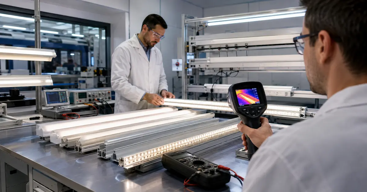
Rule of thumb: if the strip is above ~10W/m and runs long hours, provide a metal heat path. Test the full assembly (strip, profile, diffuser, end cap, mount, driver) for thermal behavior.
Thermal testing should include thermal cycling, steady-state temperature measurement with thermocouples at the PCB near LEDs, and infrared imaging to identify hotspots. Record temperatures at specified ambient conditions (for example 25 °C and 40 °C) and compare them to LED manufacturer maximum junction temperature recommendations. If necessary, increase copper weight on the PCB, use wider thermal pads, or relocate the driver externally to reduce local heat.
| Design factor | Risk if ignored | Practical action |
|---|---|---|
| Profile mass | Higher temperature | Choose aluminum with sufficient mass |
| Diffuser opacity | Light loss and heat | Test lux after diffuser |
| Adhesive surface | Peeling and poor transfer | Clean, degrease, press evenly |
| Driver location | Heat near LEDs | Keep drivers ventilated |
| Continuous run length | End dimming and heat load | Feed power at intervals |
Service guidance: specify clip spacing (e.g., every 200–300 mm depending on weight and vibration), adhesive type, and any mechanical back-up required for vibration zones.
7. What IP rating and material protection are needed in train interiors?
Train interiors face cleaning spray, dust, hand contact, condensation near doors, and vibration, so the IEC explanation of IP ratings is useful when evaluating protection against solid objects and water ingress. IP needs depend on location. IP20 can be acceptable inside covered coves, while a properly specified waterproof COB LED strip may be more appropriate for door zones, dining spaces, toilets, condensation-prone areas, and locations exposed to frequent cleaning. Higher IP can trap heat—pair rating with thermal design.
Specify chemical resistance properties for coatings and diffusers. Cleaning agents used on fleets (alkaline cleaners, disinfectants containing quaternary ammonium compounds, or alcohol-based wipes) can attack silicone or acrylic coatings. Request supplier chemical resistance data or run your own wipe tests with the fleet’s actual cleaners.
| Protection level | Typical structure | Best train location | Watch point |
|---|---|---|---|
| IP20 | Bare PCB in profile | Dry hidden coves | Needs touch protection |
| IP54 | Light coating | Dust-prone panels | Limited liquid protection |
| IP65 | Silicone coating or extrusion | Door zones, dining cars | Check heat rise |
| IP67 | Sealed sleeve or extrusion | Damp entrance areas | Harder to service/cool |
| IP68 | Fully sealed product | Washdown zones | Usually over-specified for cabins |
When specifying higher IP ratings, include test cycles for temperature rise and require suppliers to submit measured lumen output and case temperature for sealed units to ensure life expectancy is not compromised.
8. How should drivers, dimming, and control systems be planned?
Drivers must match voltage, wattage, and vehicle power conditions. Size drivers at ~80% load for long-hour systems. Choose dimming protocols early (PWM, 0–10V, DALI, DMX, or vehicle bus) and test interfaces before mass production. Ensure EMC-suitable converters for rail use and add surge protection where needed.
Consider the vehicle control architecture — some fleets use CAN, LIN, or proprietary vehicle networks. Plan an interface board or gateway early, and procure drivers with documented dimming curves so the lighting designer can predict correlated color shift during dimming. Also verify driver flicker metrics and review the common causes of flickering LED strip lights, specifying an acceptable flicker percentage and frequency where passenger comfort or camera recording is a concern.
| Driver topic | Recommended practice | Business impact |
|---|---|---|
| Load margin | Use ~80% capacity | Reduces warranty risk |
| Flicker | High-frequency PWM or tested dimming | Improves comfort |
| EMC | Rail-suitable converter | Avoids interference |
| Surge protection | Add at input stage | Reduces random failures |
| Access | Serviceable mounting | Cuts maintenance labor |
Include firmware or configuration control in the procurement so dimming behavior can be updated if the vehicle control system is changed. For systems relying on PWM, test at low dim levels for visible flicker on camera and for LED color shifts.
9. What installation details reduce failures and callbacks?
Installation quality is critical, so installers should follow professional LED strip light wiring practices for cable sizing, power injection, connectors, polarity, insulation, and strain relief. Build a mock-up bay and dry-fit before full installation. Clean mounting surfaces thoroughly, use mechanical clips in vibration zones, provide strain relief at solder joints, and plan power injection for long runs. Label cables and circuits to speed maintenance.
Training and clear installation drawings cut failures. Provide installers with a quick-reference checklist and require that the installation be inspected by a qualified technician before panels are closed. If adhesives are used, specify cure time before the vehicle returns to service and avoid subjecting newly bonded assemblies to high humidity or heat until the adhesive has set.
| Installation checklist item | Pass criteria | Failure if skipped |
|---|---|---|
| Surface cleaning | No dust or oil | Adhesive lifting |
| Dry fit | Length and exits verified | Rework and waste |
| Bend radius | No sharp folds | Broken tracks |
| Strain relief | No pull on pads | Intermittent faults |
| Power injection | Brightness within range | Visible dimming |
| Final burn-in | Stable light after test | Early site failures |
Field tip: retain a small spare reel of the exact batch used and a set of spare drivers and connectors with each trainset so quick repairs can be made to match color and binning without sourcing a new batch during service operations.
10. How should quality testing and supplier documentation be reviewed before purchase?
Request datasheets, lumen/CCT/CRI reports, driver certificates, batch labels, and sample approval records. Perform integrating-sphere tests, aging racks, thermal imaging, dimming tests, and vibration mounting review. Inspect packaging to prevent transit damage.
Testing protocols should include a minimum burn-in of 24–72 hours depending on the risk profile, while broader environmental testing should cover vibration under IEC 61373 where applicable and thermal cycling between the expected minimum and maximum cabin temperatures. Require suppliers to provide test reports and allow witnessing of critical tests during sample approval.
| Common failure mode | Likely cause | Quick fix | Long-term prevention |
|---|---|---|---|
| End of strip looks dim | Voltage drop | Add power feed | Use 24V or zone wiring plan |
| Strip peels off | Poor surface prep or heat | Rebond with clips | Use aluminum profile and cleaning SOP |
| Flicker during dimming | Driver mismatch | Replace driver | Test dimming protocol early |
| Color mismatch | Mixed batches | Replace affected section | Specify SDCM and batch control |
| Early LED failure | Heat or overdrive | Reduce load | Thermal test full assembly |
| Random outage | Loose solder or cable strain | Repair joint | Add strain relief and inspection |
Require suppliers to provide traceable batch numbers on reels and to keep a small quantity of each batch for a defined period to allow matching during future maintenance or repairs. Also confirm packaging protects against flex, crush, and moisture during rail-specific logistics.
Conclusion
Train compartment lighting must be specified as a complete system: strip type, voltage, driver, profile, diffuser, wiring, protection, and testing. Focus on heat management, color consistency, dimming compatibility, and mechanical fixing to withstand vibration and cleaning routines. Use mock-ups, sample approvals, and clear installation drawings to reduce on-site rework and maintenance. When in doubt, share drawings with engineering for a practical test plan.
Add a delivery and spares plan to your contract: list spare reels, drivers, connectors, and a small stock of matching diffusers so the maintenance depot can replace parts without introducing color shifts. Define warranty terms that cover color shift, early lumen loss, and adhesive failures under specified operating conditions.
FAQ
Q1: What are led strip lights for train compartment use?
They are low-profile linear LED lights designed for rail cabin areas such as sleeper rooms, passenger seats, luggage racks, corridors, and service panels. They require vibration resistance, stable drivers, controlled heat, and consistent color.
Q2: Is 12V or 24V better for train compartment LED strips?
For medium-length cabin runs, 24V is usually better because it reduces current and voltage drop. 12V works for short task lights. Consider cable size and driver layout.
Q3: What color temperature is best for passenger train cabins?
Most passenger areas use 3000K–4000K. Sleeper cabins often aim for 2700K–3500K. Corridors and luggage areas can use 3500K–5000K for clear visibility. Maintain tight CCT binning.
Q4: Do train compartment LED strips need waterproof protection?
Not always. Dry hidden coves can use IP20 in a covered profile. Door areas, dining spaces, toilets, and cleaning-exposed zones may need IP65 or higher. Match IP rating with heat design.
Q5: How can I reduce maintenance problems after installation?
Use proper voltage planning, quality drivers, aluminum profiles, clean mounting surfaces, strain relief, batch-controlled strips, and a burn-in test before handover. A mock-up inside the actual compartment is one of the best ways to catch issues early.
