
This V-Shape LED Channel Guide explains how a V-shape LED channel—a 90° aluminum profile designed for corner installations—holds LED strip lighting and directs light outward instead of straight down. When paired with the right diffuser and strip, it reduces glare, hides hotspots, protects the tape, and delivers a clean, repeatable finish for cabinets, shelving, coves, and displays.
Corner lighting looks simple until you’re the one handling complaints: visible dots, uneven brightness, early strip failures, and messy silicone “fixes” that eat margin. The solution is not just “stronger strip” or “more wattage.” It’s choosing the right V-profile, lens, strip type, wiring plan, and mounting method as a system. Most corner failures trace back to a few predictable spec mismatches—and they’re preventable.
1. What is a V-shape LED channel, and what problems does it solve?

V-shape channels (also called 90-degree corner profiles) are aluminum extrusions with a V cavity that holds an LED strip and a snap-on diffuser. Their job is mechanical protection, light shaping, and heat spreading.
Glare control is the big win. In a kitchen under-cabinet corner, a bare strip can hit the eye line and look harsh. A V-profile shifts the emission angle so the user sees reflected light on the counter or backsplash, not direct LED points.
Protection is the quiet win. Installers often damage tape edges during cabinet work; cleaners and chemicals also take a toll over time. A profile shields the strip and keeps the lens as the “wear surface” you can replace.
Consistency is the commercial win. Retail shelves, hotel joinery, and branded displays need repeatable geometry. A V-channel standardizes LED position, lens alignment, and the final line of light.
| LED profile type | Typical mounting location | Light direction | Typical use case | Primary risk if misused |
|---|---|---|---|---|
| V-shape corner profile | 90° internal corners | 30–60° outward from corner | Shelves, cabinets, coves, displays | Hotspots if lens distance is too small |
| U-shape surface profile | Flat surfaces | 90° downward | Undercabinet, linear task lighting | Glare on glossy counters |
| Recessed profile | Routed channels | Controlled, flush | Furniture, architectural lines | Routing tolerance causes fit issues |
| Hanging/suspended profile | Open ceilings | Down/up lighting | Offices, corridors | Driver access and servicing |
2. Where do V-shape LED channels work best in real installations?

Corner profiles work wherever you need a “wash” across two planes—wall-to-ceiling coves, shelf-to-backpanel corners, and display cases where the light should feel indirect.
We’ve seen premium retail displays fail inspection because a flat-mounted strip produced harsh reflections in glass and glossy packaging. Switching to a V-channel aimed the light into labels and softened glare where customers actually look.
In joinery-heavy projects like hotel corridors, inside corners are often chosen to hide the fixture. A V-profile helps the line read as continuous even when carpentry joints vary slightly, because the light is thrown outward instead of exposing the corner edge.
In industrial control cabinets, V-profiles are used on door corners for service lighting. The channel protects the strip from abrasion, and the angled light reduces shadows on terminals.
Typical applications you’ll see:
- Retail shelf edge and back corner illumination
- Display cabinets (jewelry, cosmetics, electronics)
- Stair skirt board corners and handrail recesses
- Cove lighting in gypsum corners (with proper heat and driver planning)
- Machine enclosures and inspection benches
V-channels aren’t only “for looks.” They reduce callbacks by controlling where light goes and by shielding LED tape from the real-world abuse that happens after handover.
3. How do you choose the right V-profile size and match it to the LED strip?
Start with physical fit, then optical spacing, then heat.
Physical fit: measure the LED strip PCB width (8 mm, 10 mm, 12 mm are common). You want clearance so the strip doesn’t buckle during installation. For high-density or COB strips, also check adhesive thickness and solder pad height so the tape sits flat.
Optical spacing: the distance from LEDs to diffuser matters. Too shallow and you see dotting. Too deep and you can lose intensity where you need it (especially with opal lenses).
Heat: higher-watt strips need thicker aluminum and solid mounting contact. A corner profile floating on foam tape won’t remove heat like one screwed into a metal frame.
Field examples:
- A museum case using 3000K COB at 10–12 W/m worked well in a compact V-profile because COB has no discrete points.
- A convenience store shelf using 120 LED/m SMD showed dots through a clear lens; a deeper profile plus opal lens solved it.
- A bar counter using 14.4 W/m SMD ran hot in a small profile on wood; mechanical mounting into a metal subframe reduced surface temperature noticeably.
| Strip attribute | What to check | What can go wrong in a V-profile | Practical selection note |
|---|---|---|---|
| PCB width | 8/10/12 mm | Strip won’t seat flat | Leave 0.5–1.5 mm clearance |
| LED density | LEDs/m | Dots visible | Higher density or deeper profile |
| Wattage per meter | W/m | Lumen drop over time | Use thicker profile and better mounting contact |
| CCT/CRI | Kelvin, CRI | Batch mismatch shows in corners | Specify binning and batch control |
4. How do diffuser and lens choices change glare, dot-free effect, and output?

Lens choice decides what the end user perceives. Clear lenses keep output high but show points unless LED density is high and the profile provides enough depth. Opal/frosted lenses hide points and soften reflections, but they also absorb some lumens.
In our lab tests using integrating spheres, a typical opal diffuser can reduce delivered lumens by roughly 15–30% depending on material and thickness. That isn’t “bad.” It’s a trade: less glare and better uniformity versus raw output.
Three situations where lens choice drives results:
- Luxury retail: opal lens to avoid sparkles on glossy packaging, even if you raise wattage slightly.
- Workshop cabinet: clear or semi-frosted lens to keep task brightness high, because glare is less of a concern.
- Hotel cove: deeper V-profile with opal lens, so the light reads as a soft wash on the wall, not a line of points.
One practical catch: lens fit and end caps affect maintenance. If the lens can be popped out easily, it will be—especially in public spaces. For higher-traffic sites, choose tighter snap geometry or use locking clips.
| Diffuser type | Visual effect | Typical light loss | Where it fits | Common complaint |
|---|---|---|---|---|
| Clear | Sharp, bright | 5–12% | Task lighting, short runs | LED dots visible |
| Semi-frosted | Balanced | 10–20% | Shelves, cabinets | Slight doting on low density strips |
| Opal/milky | Smooth line | 15–30% | Retail, hospitality, coves | “Not bright enough” if wattage not adjusted |
| Prismatic | Controlled glare | 10–25% | Offices, reflective surfaces | Pattern visible at close distance |
5. How does heat management work in a V-shape channel, and why does it affect lifetime?
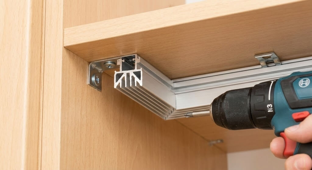
LED tape rarely fails from “being LED.” It fails from heat and electrical stress. A V-profile helps by spreading heat into aluminum, then into the mounting surface.
On aging racks we see the same pattern: strips running hot lose flux faster, adhesives soften, and solder joints fatigue. That shows up as dim segments, color shift, lens yellowing near hotspots, or intermittent flicker.
In thermal imaging checks, the same 12 W/m strip can run 8–15°C cooler when bonded to a thicker aluminum profile and screwed into a metal cabinet frame, compared with sticking it directly on MDF. That temperature drop can be the difference between stable output and early warranty noise.
Examples that show up in the field:
- In a restaurant banquette corner, the channel was glued to painted wood and eventually released. Switching to screws into a hidden aluminum angle improved both heat transfer and retention.
- In a refrigerated display, condensation attacked weak adhesives. A profile with mechanical clips kept the strip flat and improved serviceability.
- In a signage lightbox corner, an overdriven strip ran hot. A larger V-profile plus a correctly loaded driver kept brightness stable.
| Profile feature | Heat effect | What to specify | Why it matters to liability and service |
|---|---|---|---|
| Aluminum thickness | Higher mass spreads heat | 1.0–2.0 mm typical | Lower hotspot temperature reduces early failures |
| Mounting method | Contact area controls conduction | Screws/clips beat foam tape | Less drop-off, fewer detachments |
| Surface finish | Affects corrosion, not heat much | Anodized for humid areas | Fewer corrosion-related shorts |
| Max recommended load | Prevents overdriving | Ask for W/m guidance | Avoids accelerated lumen depreciation |
6. How do voltage, wiring, and drivers change corner-run performance?
Voltage drop is the silent killer in long runs. A V-profile doesn’t fix it—it just makes the installation look clean while the electrical problem develops until the client notices uneven brightness.
If you feed a 12V strip from one end on a long corner, the last meters often run warmer color and lower brightness. Feeding from both ends, moving to 24V, using heavier gauge wire, or using constant-current solutions can stabilize the line.
Three project patterns:
- Retail shelving: many short segments. 24V with parallel homeruns reduces troubleshooting time.
- Hotel coves: long continuous corners. Feed from both ends or inject power every 5–10 m depending on load.
- Furniture OEM: fixed-length modules. Pre-wired harnesses with labeled connectors cut onsite errors.
Driver choices matter too. Wrong dimming protocol (0–10V, PWM, DALI) can cause flicker on camera, and poor driver quality can cause inconsistent dimming between zones.
| Parameter | 12V strip system | 24V strip system | Field impact |
|---|---|---|---|
| Current for same wattage | Higher | Lower | Lower current reduces voltage drop and wire size stress |
| Typical max single-end feed length | Shorter | Longer | More uniform corners on long coves |
| Cutting increment | Often 3 LEDs | Often 6 LEDs | Affects how cleanly yo
u fit corner lengths |
| Driver availability | Very common | Very common | Both workable; 24V simplifies long runs |
7. How do you cut, join, and mount V-shape channels without visible gaps?
Corner work is unforgiving. Any mismatch can show as a light leak, a shadow line, or a crooked reflection.
Cutting: use a miter saw with a non-ferrous blade. Deburr the aluminum, then test-fit the lens. A small burr can stop the diffuser from snapping in fully and can telegraph as a gap.
Joining: for continuous corners, plan where joints fall. Put joints behind dividers, shelf brackets, or signage frames so minor seams don’t sit in the viewing zone.
Mounting: screws and clips beat double-sided tape for long-term stability, especially on painted or dusty surfaces. Tape can work for short cabinet pieces if the surface is degreased and flat, but it should not be your only retention method on long runs.
Installers often struggle with inside-corner alignment in MDF cabinets where edges aren’t perfectly 90°. A thin foam gasket behind the profile can hide minor carpentry error without twisting the extrusion.
| Step | What you do | What to check on site | Fast failure if skipped |
|---|---|---|---|
| Measure corner angle | Verify it’s 90° (or not) | Use a square gauge | Light line looks “open” on one side |
| Cut and deburr | Miter cut, remove burrs | Lens snaps evenly | Lens pops out later |
| Mount mechanically | Clips or screws | No rocking, full contact | Adhesive release and sag |
| Install strip | Press evenly, no bubbles | No lifted corners | Hotspots and early dark segments |
| Fit lens and end caps | Snap and seal | No light leaks at joints | Visible pinholes and dust entry |
8. How do you handle moisture, dust, and corrosion for corner channels?
A V-channel itself doesn’t make a system waterproof. The weak points are end caps, wire exits, and joints between profile pieces.
For bathrooms and kitchens, you’re dealing with steam, cleaners, and fine dust. Use anodized aluminum, choose end caps with gasket features, and seal wire exits with neutral-cure silicone compatible with the strip.
For outdoor facade corners, UV and temperature swings matter. Lenses can yellow or become brittle if the plastic grade is wrong. Near coastal areas, corrosion resistance and fastener choice become as important as optics.
Three field examples:
- A spa ceiling cove used IP65 strip but left end caps unsealed. Moisture migrated into the profile and caused intermittent shorts.
- A cold-room corner used standard steel screws that rusted and stained the panel. Swapping to stainless fasteners fixed the cosmetic issue.
- A bus shelter lightbox used a clear lens that yellowed. Choosing UV-stable diffuser material avoided a mid-season rework.
| Environment | Suggested strip rating | Profile/lens notes | Sealing focus point |
|---|---|---|---|
| Dry indoor (retail, office) | IP20 | Any diffuser; focus on glare | Dust management at joints |
| Kitchen/bathroom | IP44–IP65 | Anodized profile; gasketed caps | Wire exit and cap perimeter |
| Outdoor sheltered | IP65 | UV-stable lens | Joints and mounting holes |
| Outdoor exposed | IP67/IP68 modules | Consider potted strips or neon flex | End caps, drain strategy, service access |
9. What are common misconceptions that cause corner lighting failures?
Common myth: higher wattage always means better brightness. Reality: efficacy (lm/W), optics, and glare control determine what the user perceives. A lower-watt, higher-efficacy tape behind an opal lens can look brighter on the wall because it reduces sparkle and spreads light more evenly.
Another myth: “Any diffuser will hide dots.” Dot-free results come from the full stack: LED pitch, diffuser type, and LED-to-lens distance.
A third myth: “Tape adhesive is a mounting method.” It’s not. It’s a positioning aid—and it’s one of the first things to degrade when heat and cleaners show up.
Callback drivers we see repeatedly:
- Color mismatch between batches in long hotel corridors
- LED Flicker on dimming due to driver-strip mismatch
- Dark tail-end segments from voltage drop
| Symptom on site | Likely root cause | Fast diagnostic | Practical fix |
|---|---|---|---|
| Bright near feed, dim at end | Voltage drop | Measure voltage at far end | Power injection, 24V, thicker wire |
| Visible dots through lens | Low density or shallow profile | View at 1–2 m distance | Opal lens, higher density, deeper profile |
| Lens pops out | Burrs or wrong cut angle | Check ends and snap fit | Deburr, replace lens, add clips |
| Strip peels off | Heat + poor surface prep | Check substrate temp and paint | Screws/clips, clean with IPA, use primer |
| Flicker on camera | PWM/dimming mismatch | Test at 10–30% dim | Change driver, raise PWM frequency |
Most of these fixes cost little if you plan them before you cut aluminum. They cost a lot after client sign-off.
10. What specs and checks should you request to standardize projects and reduce risk?
If you manage multiple sites, your spec sheet should prevent “same part number, different outcome.” That means defining geometry, optics, and electrical behavior in writing.
From our manufacturing floor perspective, the best RFQs include a drawing (profile cross-section), lens material, finish, mounting method, and the strip details in the same document. That prevents the classic mismatch: a 12 mm strip ordered, a 10 mm cavity profile delivered.
Three scenarios where specs protect margin:
- Franchise rollouts: one bad batch of CCT ruins store uniformity.
- Furniture OEM: a profile tolerance shift breaks assembly jigs.
- Public projects: missing certifications creates customs or inspection delays.
Ask for:
- Dimensional tolerances on profile width and lens fit
- Anodizing or coating spec for corrosion exposure
- Lens transmittance and UV stability notes
- Strip binning (CCT tolerance), CRI, and test reports
- Driver parameters: load range, dimming type, flicker performance
Pro Tip (VST Technical Team): “Treat the channel, strip, and driver like a matched set. If you swap one part, recheck heat, voltage drop, and lens uniformity.”
| Item to confirm | What to request | Why it protects your site result |
|---|---|---|
| Profile drawing | Cross-section + cavity width | Prevents strip fit issues |
| Lens type | Opal/clear + material grade | Controls glare and yellowing risk |
| Surface finish | Anodized grade/color | Reduces corrosion and visual mismatch |
| Strip spec | W/m, LEDs/m, CCT bin, CRI | Keeps brightness and color consistent |
| Test evidence | Sphere data, aging photos, QC notes | Verifies claims before volume rollout |
Conclusion
V-shape channels solve corner glare, protect LED tape, and make installations repeatable. The best results come from matching profile depth, diffuser choice, heat path, and wiring plan—not from chasing wattage. For shelf systems, hotel coves, or OEM fixtures, write the spec as a full system and validate one sample run before rollout. If you’re unsure about voltage drop or thermal load in your corner layout, send our engineering team your drawing and target lux level for a quick sanity check.
FAQ
Q1: What is a V-shape LED channel?
A V-shape LED channel is a 90° aluminum profile that holds LED strip lighting in corners, aiming light outward for a smoother wall or shelf wash while protecting the strip and diffuser.
Q2: How does a V-profile reduce glare compared with a flat-mounted strip?
It changes the emission direction so the brightest points are not directly in the viewing angle. With an opal lens, it also spreads light, which lowers harsh reflections on glossy surfaces.
Q3: Can I use high-watt LED strips in a small V-shape channel?
You can, but heat rises fast if the profile mass is low or the mounting surface is wood. Check the W/m load guidance, mount with screws or clips, and verify temperature with a simple spot check after 30–60 minutes.
Q4: What voltage is better for long corner runs, 12V or 24V?
24V is usually easier for long runs because current is lower for the same wattage, so voltage drop is reduced. For very long lines, power injection or segmented feeds still apply.
Q5: Why do I still see LED dots through a diffuser?
Dotting usually means the LED pitch is too wide for the profile depth and diffuser type. A deeper profile, higher LED density, COB tape, or a more opaque diffuser can smooth the line.
