
COB LED strips should only be cut at the marked cut points printed on the strip, usually shown by a scissors icon, a straight line across the strip, or copper pad markings. Cutting anywhere else can break the circuit, damage LED sections, and cause partial failure. If you need a short, direct answer to where to cut cob led strip, cut only on the factory-marked intervals and confirm the voltage, pad layout, and connector method before making the cut.
Where to Cut COB LED Strip is a question that sounds simple, but a wrong cut can turn a clean installation into wasted material, dark sections, and jobsite delays. We often see installers struggle with this when they assume COB strips can be cut anywhere because the light output looks continuous. That is not how the circuit is built. In our lab tests using integrating spheres and routine production checks, the cut interval and pad structure always determine whether the strip will perform safely after trimming. This article explains exactly how to identify the correct cut position, what changes between 12V and 24V products, and how to avoid mistakes that hurt both reliability and installation efficiency.
1. What makes COB LED strips different from standard LED strips?
COB LED strips, including a COB 10mm LED light strip, look very different from standard SMD strips. On a normal SMD strip, you can see each LED package and usually spot the circuit segments with little effort. On a COB strip, the phosphor coating creates a smooth line of light, so the electrical segmentation is less obvious. That is where many cutting mistakes begin.
From our manufacturing floor perspective, COB strips are built with densely packed chips mounted directly on the flexible board. The visual effect is cleaner, especially in aluminum profiles, furniture channels, retail shelving, and cove lighting. But here’s the catch: the continuous light line does not mean a continuous cut area. The strip still follows fixed electrical sections.
We once saw a display cabinet project where an installer cut between markings because the phosphor layer hid the copper pads. The result was a dead end section and a rework delay. In a hotel corridor, that kind of mistake can affect multiple rooms. In a shelf-lighting project, it can create visible dark spots right before handover.
COB manufacturing also often integrates a thin protective lacquer or silicone layer to improve lifetime and color consistency. That finish can hide PCB details but it does not change the underlying electrical segmentation. Production test points and printed segment outlines are placed before conformal coating, so trusting visual cues alone is risky. For engineers and procurement teams, specifying clearly marked cut points and requesting detailed datasheets from suppliers reduces on-site confusion.
| Feature | COB LED Strip | Standard SMD Strip |
|---|---|---|
| Light appearance | Dotless and uniform | Visible LED points |
| Cut visibility | Less obvious without close check | Usually easier to identify |
| Installation look | Better for premium lines | Acceptable for basic use |
| Risk of wrong cut | Higher if markings are ignored | Moderate |
| Common application | Profiles, cabinetry, display lighting | General accent lighting |
2. Where exactly should you cut a COB LED strip?
The correct place to cut a COB LED strip is on the printed cut line provided by the factory. This line normally runs across the strip between two copper solder pads. Many products also include a scissors symbol. If you do not see that mark clearly, stop and inspect the strip under better light before cutting.
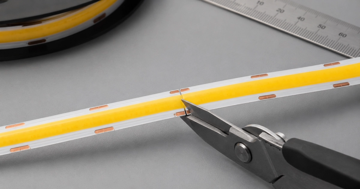
Do you know how to cut Cob LED Strip? Ready for the good part? The actual cut point is not chosen by appearance. It is chosen by circuit design. Each segment has a set number of LEDs and resistive or regulated components matched to the strip voltage. If you cut outside that interval, the next section may not receive proper power.
We often see three field scenarios. One is cabinet lighting, where the installer trims a strip to fit a profile. Another is mirror backlighting, where tight dimensions lead to rushed cuts. The third is retail fixture production, where teams cut dozens of pieces in batches. In every case, using only marked cut lines avoids scrap and callbacks.
A useful on-site verification is to measure continuity across the copper pads with a multimeter set to continuity mode. This confirms which pads form the segment boundary and helps you identify the correct cutting plane even when markings are faint or hidden under a coating. If continuity shows multiple pads bridged beyond an expected segment length, consult the datasheet—some strips use hidden traces or staggered layouts to achieve even light output.
| Visual marker | What it means | Action |
|---|---|---|
| Scissors icon | Approved cut location | Cut on the center line |
| Copper pads on both sides | Reconnection point | Leave enough pad area intact |
| Printed line across strip | Segment boundary | Use sharp flush cutters or scissors |
| No visible mark | Do not guess | Check datasheet or product label |
If you want to get more clear idea, read our guide about cutting cob led strip light.
3. How do voltage and circuit design affect cut intervals?
Voltage changes the cut interval. A 12V COB strip usually has shorter cut segments than a 24V COB strip. That matters a lot if you are fitting strips into short aluminum channels, small display cases, or custom furniture.
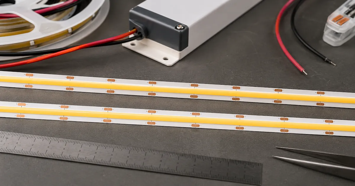
When we tested this against a standard 12V strip, the shorter cut interval gave more layout flexibility, but it also raised current levels for the same power over the same length. A 24V strip often gives fewer cutting points, yet it handles longer runs better with less visible voltage drop. So the best cutting interval is not only about convenience. It is tied to the full electrical plan.
Common myth: all COB strips can be cut at the same spacing. Reality: cut length depends on board design, voltage, wattage, and current path. We explain this because ignoring it leads to wrong material planning, poor fit inside profiles, and wasted stock.
It is also worth noting how segments are wired internally: many COB strips use groupings of chips in series with current-limiting resistors or constant-current drivers per segment. Changing the segment count by cutting alters the per-segment forward voltage and current distribution across the run. Thermal management is another consideration—shorter segments concentrate more current per segment and can increase localized heating, so ensure your profile and adhesive can dissipate heat properly.
| Specification | 12V COB Strip | 24V COB Strip |
|---|---|---|
| Typical cut interval | Shorter | Longer |
| Layout flexibility | Better for tight spaces | Better for longer runs |
| Current per same wattage length | Higher | Lower |
| Voltage drop risk on long runs | Higher | Lower |
| Typical use case | Small fixtures, short customized cuts | Long linear runs |
4. How can you identify cut marks when the strip surface looks continuous?
This is where many users hesitate. COB strips hide the light points, and the phosphor layer makes the board look almost seamless when powered off. Still, the cut marks are there. You just need a systematic check.
I suggest looking for four things: the printed scissors symbol, the black or white cut line, the exposed copper pads, and the repeating segment layout. Use bright bench lighting. If the strip is silicone-coated, inspect from an angle because the mark can disappear under glare.
In our lab tests using integrating spheres, optical performance is measured after the strip is built, but the mechanical usability of cut points is just as practical for field work. We often see installers struggle with IP-coated versions because the surface finish hides the pad border. On one facade sample, the cut line was visible only after wiping off surface dust. On a vanity mirror project, the contractor marked all cut positions with a fine pen before touching scissors. That saved time and reduced errors. On a furniture line assembly, workers used a printed jig to align repeated lengths.
Practical step-by-step for hard-to-see marks:
- Clean the area with isopropyl alcohol to remove dust and coating residues that can hide printing.
- Use a magnifier or headlamp with a focused beam to reveal subtle printed lines.
- If permitted, flex the strip gently to find the natural segment break stiffness—often the PCB will flex more at the segment boundary.
- Cross-check with the reel label and datasheet which normally lists the exact mm length of each segment.
| Identification method | Best use | Notes |
|---|---|---|
| Scissors icon | Fast visual check | Most reliable if printed clearly |
| Copper pad location | Re-soldering jobs | Pads must remain usable after cut |
| Datasheet segment drawing | Production planning | Best for batch processing |
| Test fit before cut | Profile installation | Reduces waste on custom lengths |
5. What tools and preparation give you a clean, safe cut?
A clean cut starts before the blade touches the strip. Use sharp scissors for low-volume work or flush cutters for better precision. For production use, a fixed cutting jig works better. A dull tool can tear the PCB edge, lift the coating, or deform the copper pads.
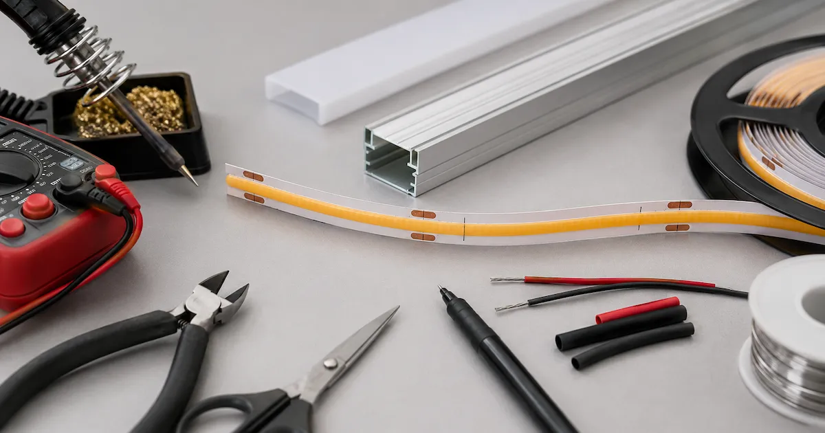
Here’s the deal. Preparation matters just as much as the tool. Disconnect power. Confirm the exact final length. Dry-fit the strip inside the profile or mounting channel. Mark the cut line clearly. If the strip will be reconnected, leave the pad area clean and accessible.
We once saw three different outcomes from the same product. In a shopfitting project, a clean flush cut allowed quick soldering and zero visible damage. In a contractor workshop, blunt scissors damaged the pad and forced a second cut, making the strip too short. In a signage job, the team forgot to test-fit the cable exit direction before trimming, which caused another delay.
Additional recommended tools and consumables:
- Small bench vise or strip holder to keep the strip straight when cutting multiple pieces.
- Razor blade or precision utility knife for trimming silicone jackets after cutting (careful not to nick the PCB).
- Small wire stripper and heat-shrink tubing for tidy terminations.
- Flux and rosin-core solder for quicker, cleaner joints when soldering to pads.
| Tool or step | Recommended use | Risk if ignored |
|---|---|---|
| Sharp scissors | Small jobs | Ragged edge |
| Flush cutter | Cleaner pad access | Less risk of board damage |
| Fine marker | Accurate cutting | Wrong segment length |
| Power off check | Safety | Short circuit risk |
| Dry-fit in profile | Confirms final size | Material waste |
6. What should you do after cutting the strip?
After cutting, inspect the end immediately. Check that the copper pads are intact, the board is not cracked, and the phosphor layer has not peeled back near the cut line. Then test the strip before final mounting. This simple step avoids hidden failures later.
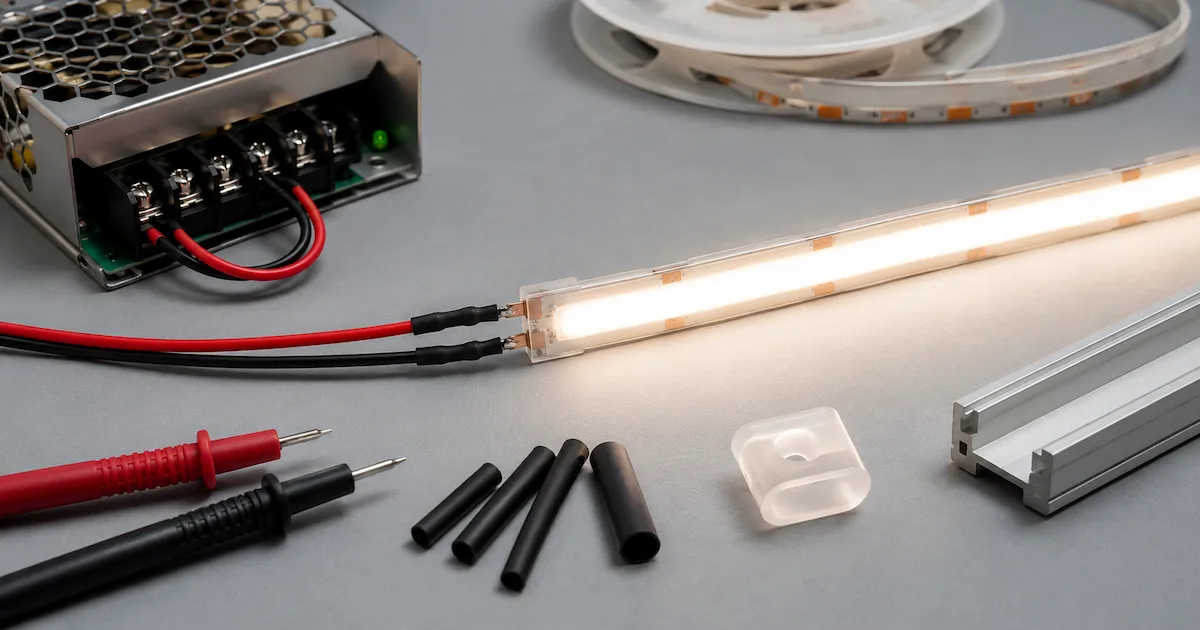
From our manufacturing floor perspective, post-cut handling is often ignored. Yet many field issues happen after a correct cut, not during it. Pads get overheated during soldering. Silicone caps are not sealed properly. Wires pull at the end termination. In a humid location, an open cut end without sealing can lead to corrosion over time.
A good workflow is straightforward. Cut the strip. Inspect the edge. Tin the pads if soldering. Connect wires with polarity check. Power-test on the bench. Only then fix it into the profile with adhesive or clips. We explain this because a failed end connection can create service calls that cost more than the strip itself.
Soldering technique notes:
- Use low-wattage temperature-controlled iron (20–40W) and work quickly to avoid lifting pads or damaging nearby components.
- Apply a small amount of flux, tin the wire and pad, then solder—this produces a reliable mechanical and electrical bond.
- After soldering, add strain relief: a dab of hot glue, a cable tie under the wire, or adhesive-lined heat shrink helps prevent repeated flexing from breaking the joint.
| Post-cut check | What to verify | Why it matters |
|---|---|---|
| Pad condition | Copper remains complete | Needed for reliable connection |
| Strip end shape | No cracking or delamination | Prevents early failure |
| Polarity marking | Positive and negative correct | Avoids non-start or damage |
| Bench test | Full section lights evenly | Finds issues before install |
| End sealing | Needed on coated strips | Reduces moisture risk |
7. Can you cut waterproof or silicone-coated COB LED strips the same way?
You can cut them at the same marked electrical points, but the handling is different. Waterproof or silicone-coated COB strips add another layer that must be cut neatly and sealed again if the strip remains exposed to moisture, dust, or cleaning chemicals.
But there’s a catch. Many installers focus only on the electrical cut point and forget the environmental rating. Once you cut an IP65 or IP67 product, that protection is interrupted at the end unless you reseal it with the proper end cap, silicone, or approved sealing method.
We have seen this in three practical settings. In bathroom mirror lighting, an unsealed cut end slowly discolored after repeated humidity cycles. In a refrigerated display, poor end sealing led to moisture ingress near the pads. In an outdoor handrail sample, the strip worked at handover but failed months later because the cut end was left exposed.
Recommended sealing options and tips:
- Use manufacturer-specific end caps and silicone seals where available for best compatibility.
- For field sealing, neutral-cure silicone is preferred—avoid acidic silicones that can corrode copper pads over time.
- For quick repairs, a two-part epoxy or UV-curing resin can restore mechanical protection but check thermal and flex compatibility first.
- Ensure the cable exit is sealed with a grommet or resin to resist wicking along the conductor into the strip.
| Strip type | Cut method | Extra action required |
|---|---|---|
| Non-waterproof | Cut on marked line | Basic inspection only |
| Silicone-coated IP65 | Cut on marked line | Reseal cut end |
| Sleeve or tube protected | Cut on marked line with care | Restore end protection |
| Outdoor rated strip | Cut only if allowed by spec | Use approved sealing system |
8. What mistakes cause damage when cutting COB LED strips?
Most cutting failures come from simple habits. People guess the cut point, use the wrong tool, cut while the strip is loosely twisted, or reconnect the strip without checking polarity. Small mistakes create expensive rework when multiplied across a project.
What’s the real story? The most common problem is not the cut itself. It is poor process control. We often see installers struggle with rushed batch cutting, especially on site under weak lighting. One wrong segment in a 50-piece run can throw off an entire fixture schedule.
A few examples stand out. In a restaurant cove lighting job, strips were cut one segment short because measurements ignored connector space. In a retail shelving build, the team cut through half of a pad, which made soldering unreliable. In a joinery workshop, adhesive backing was peeled too early, and the strip bent sharply during cutting, cracking the board.
How to prevent these mistakes:
- Use a dedicated cutting station with good lighting, marking tools, and a holder to keep strips straight.
- Train crews on the specific product family—they must know the segment length and connector footprint before they cut.
- Label pre-cut pieces as you go so inventory and assembly teams can match parts to specific fixtures and avoid mixing sizes.
| Common mistake | Typical result | Practical fix |
|---|---|---|
| Cutting off-mark | Dead segment | Follow printed cut line only |
| Damaging copper pad | Poor reconnection | Use sharp tool and center cut |
| No bench test | Hidden failure after install | Test each cut piece |
| No sealing on IP strip | Moisture damage | Seal immediately |
| Ignoring connector space | Strip too short | Measure full assembly length |
9. How do connectors, soldering, and profiles affect your cut plan?
Your cut point is only one part of the layout. You also need to think about how the strip will reconnect, where the wire exits, whether a solderless connector fits the strip width, and how the piece sits inside the aluminum profile.
In our lab tests using integrating spheres, we focus on output and uniformity, but from installation feedback, mechanical fit causes just as many complaints as electrical issues. A perfect cut is useless if the connector lifts the diffuser, blocks the profile end cap, or creates a shadow line near the entry point.
We once saw a luxury cabinet job where the strip length was right, but the connector body was too tall for the profile cover. In a sign box project, soldered leads were placed on the wrong side of the cut piece, forcing a twist in the strip. In a stair lighting run, choosing a shorter cut interval product reduced visible gaps at corners.
Pro Tip from the VST Technical Team: plan the cut line and the termination method together. If the installation space is tight, soldered leads often give a slimmer result than clip-on connectors.
Connector choices and considerations:
- Solderless snap-on connectors are fast but require that pad spacing and strip thickness match the connector design; check vendor compatibility charts.
- Low-profile angled connectors help in tight profiles but may increase the effective length used at the end of the strip—account for that when measuring.
- For RGB or tunable white COB-like products, ensure pin ordering and spacing match the controller and that any polarity marking is observed to avoid damage.
| Connection method | Best for | Limitation |
|---|---|---|
| Soldered wires | Tight profiles, durable connection | Needs skilled handling |
| Solderless connector | Fast field work | May not fit all COB strip types |
| Prewired factory cut pieces | Repetitive projects | Needs advance planning |
| Corner cable jump | Gaps and turns | Adds wiring points |
10. What is the best step-by-step checklist before you make the final cut?
If you want consistent results, use a checklist. This sounds basic, but it protects margin, installation time, and reliability. A COB strip is easy to trim only when the preparation is disciplined.
My recommended sequence is simple, and it also follows the same practical logic used when professionals install COB LED strip lights for clean, reliable projects. Confirm strip voltage and model. Read the datasheet cut interval. Measure the actual installation length. Account for profile end caps, connector body, and lead exit space. Mark the cut line. Disconnect power. Cut on the printed mark. Inspect the pads. Reconnect or seal. Bench-test. Then mount.
We explain this specific process because ignoring one step leads to visible problems later. In a hotel headboard project, one missed measurement caused 30 strips to be recut. In a refrigerated shelf build, skipped sealing created warranty claims. In a museum display case, early bench testing caught two damaged pieces before final installation.
To help installers, create a small laminated card with the checklist and place it at every cutting station. Include common segment lengths for the product family and a quick reference for connector part numbers so substitution errors don’t happen.
| Final cutting checklist | Pass/Fail purpose | Why it helps |
|---|---|---|
| Correct strip model confirmed | Prevents wrong cut interval | Avoids planning errors |
| Installation length measured | Fits actual space | Cuts waste |
| Connector and profile clearance checked | Confirms assembly fit | Prevents rework |
| Cut line marked clearly | Improves accuracy | Reduces pad damage |
| Bench test completed | Confirms function | Avoids callbacks |
A COB LED strip should be cut only at the factory-marked cut points, with the voltage, pad layout, sealing needs, and connection method checked before trimming. That is the practical answer to where to cut cob led strip. If you treat the strip as a circuit rather than just a flexible light line, you will get cleaner installs, fewer failures, and better use of material. If you are unsure about cut intervals, profile fit, or reconnection details for a specific project, send the drawing to an engineering team and verify it before cutting stock.
Conclusion
Cut COB LED strip only on the factory-marked cut points, and always confirm voltage, pad layout, sealing needs, and termination method before trimming. Use the checklist steps—measure, mark, power off, cut, inspect, reconnect/seal, and bench-test—to avoid rework and moisture-related failures. Treat the strip as an electrical circuit and not just a continuous light source to ensure reliable, professional installations.
FAQ
Q1: Where to cut cob led strip if there is no scissors mark?
Do not guess. Check the copper pad pattern, product datasheet, reel label, or supplier drawing. If no approved cut point is confirmed, do not cut the strip.
Q2: Can I cut a COB LED strip while it is powered?
No. Always disconnect power before cutting. Cutting a live strip can short the circuit, damage the power supply, and create a safety risk.
Q3: Can I reconnect a COB LED strip after cutting it?
Yes, if the strip has usable copper pads and the product supports soldering or compatible connectors. Test the connection before final installation.
Q4: Why does my COB strip not light after cutting?
The usual causes are cutting off the marked point, damaged pads, reversed polarity, or a poor solder or connector joint.
Q5: Are 24V COB LED strips better than 12V for cutting?
Not always. A 12V strip usually gives shorter cut intervals for tighter layouts, while a 24V strip is often better for longer runs with lower voltage drop.
