
Installing LED linear profiles means selecting the right aluminum channel, diffuser, LED strip, driver, mounting method, and wiring layout, then fixing the profile securely, managing heat, and testing the system before final closure. Done properly, it improves light quality, protects the strip, and cuts installation problems later.
If you install profiles without checking heat dissipation, cut points, mounting surfaces, or driver sizing, you risk dark spots, loose diffusers, voltage drop, rework, and client complaints. That is the problem many contractors and project teams face on site. The good news is that the process is straightforward when you follow a technical sequence. In our lab tests using integrating spheres and thermal checks, we have seen that correct profile installation improves strip stability, light uniformity, and service life. This article explains how to install LED linear profiles step by step, what mistakes to avoid, and what details matter for safety, finish quality, and long-term reliability.
1. What are LED linear profiles and why do they matter?
LED linear profiles, also called LED aluminum profiles, are aluminum housings designed to hold LED strips and cover them with a diffuser. They are used in cabinets, retail shelving, offices, hotels, furniture, corridors, and architectural details. You get a cleaner appearance, better heat transfer, and more controlled light output than with a bare LED strip.
We often see installers struggle with projects where the strip is stuck directly onto wood, painted steel, or gypsum. It may work at the start, but heat build-up, poor adhesion, and inconsistent beam spread usually show up later. In a hotel corridor, that can mean visible bright dots. In a joinery project, it can mean tape failure inside a cabinet. In a retail display, it can hurt the presentation of merchandise.
From our manufacturing floor perspective, the profile is not only a cosmetic accessory. It is part of the thermal and mechanical system. That matters to your bottom line because replacing failed strips inside finished furniture or ceiling slots costs far more than installing the right profile at the start.
| Profile Function | Why It Matters | Site Impact |
|---|---|---|
| Heat dissipation | Helps move heat away from strip PCB | Longer strip life |
| Mechanical protection | Shields strip from dust and touch damage | Fewer failures |
| Light diffusion | Reduces LED dotting and glare | Better visual result |
| Straight alignment | Keeps lines clean and consistent | Higher finish quality |
| Easier maintenance | Organized installation layout | Faster service work |
2. Which type of LED linear profile should you choose?
Not every profile fits every job. Surface-mounted profiles suit under-cabinet lighting, shelves, and retrofit work. Recessed profiles work well in ceilings, walls, and furniture where a flush finish is required. Corner profiles are useful for 45-degree lighting in cabinets, showcases, and display frames. Suspended profiles are common in offices and commercial interiors where direct or direct-indirect lighting is needed.
Here is the deal. The profile shape must match the application, but the internal width must also match the LED strip. We once saw a field case where a 12 mm COB strip was forced into a 10 mm channel. The strip bent, adhesive contact was reduced, and thermal transfer suffered. In another case, a deep profile solved the dotting problem in a premium lobby because the diffuser sat farther from the LEDs.
Common Myth: any aluminum channel will do the job. Reality: profile depth, wall thickness, mounting flange, and diffuser type all affect performance and finish.
| Profile Type | Best Use | Main Advantage | Limitation |
|---|---|---|---|
| Surface | Retrofit, cabinets, shelves | Fast installation | Visible body |
| Recessed | Joinery, gypsum, ceiling slots | Clean flush look | Requires cutout work |
| Corner | Cabinets, displays | Angled light direction | Limited placement |
| Suspended | Offices, workspaces | Wide light distribution | Needs hanging kit |
| Deep profile | Premium architectural use | Better dot-free effect | Higher material cost |
3. What tools and materials do you need before installation?
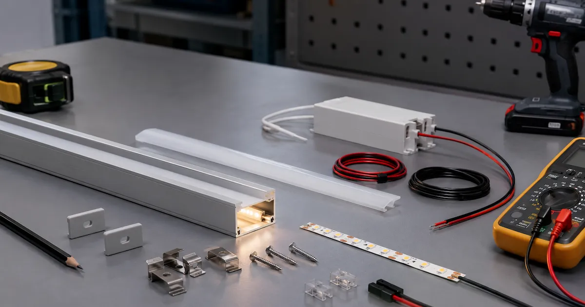
Preparation saves time. A typical installation needs the profile, diffuser, end caps, mounting clips or screws, LED strip, driver, connectors or soldered leads, cable, measuring tape, pencil, spirit level, cutting tools, drill, screws, surface cleaner, and a tester or multimeter. If the project is recessed, you may also need a router, gypsum saw, or CNC-prepared slot.
Ready for the good part? The most common delays do not come from difficult wiring. They come from missing small items. A diffuser left off the delivery list. End caps that do not match cable exit direction. Clips fixed to uneven surfaces. Driver compartments with no ventilation. These details create site friction and margin loss.
In our lab tests using integrating spheres, we focus on optical data, but on project support calls, we see installation accessories causing just as many headaches as strip performance. For example, pre-soldered leads can save a lot of fitting time in narrow channels. From our manufacturing floor perspective, planning cable exit positions before cutting profiles reduces waste and avoids last-minute drilling that can damage the finish.
| Item | Purpose | Check Before Site Work |
|---|---|---|
| Aluminum profile | Holds strip and transfers heat | Correct length and width |
| Diffuser | Softens light and protects strip | Opal, frosted, or clear type |
| End caps | Finish ends and manage cable exits | Hole or no-hole version |
| Mounting clips/screws | Secure profile | Match substrate |
| LED driver | Powers strip | Voltage and wattage matched |
| Wire/connectors | Electrical connection | Cable gauge and polarity |
4. How do you plan the layout and power correctly?
Before fixing anything, map the full run length, feed points, power supply location, and control method. Measure the real installation path, not the drawing only. Corners, bends, cabinet sides, and access points often differ from plans.Then calculate total wattage and add headroom by using a proper LED profile driver calculation before final installation.A safe practice is to keep driver loading below its maximum rating.

This is where it gets interesting. Profile installation problems are often electrical problems in disguise. Long strip runs can lose brightness toward the far end if voltage drop is ignored. We often see installers struggle with a 5-meter concept copied into a 15-meter run with a single-end feed. The result is uneven output, warm color shift, and callbacks.
When we tested this against a standard 12V strip, the brightness loss on longer runs was far more visible than on a 24V system. That is why planning matters for both visual quality and labor cost.
| Parameter | 12V System | 24V System |
|---|---|---|
| Short runs | Suitable | Suitable |
| Long runs | More voltage drop risk | Better stability |
| Current level | Higher current | Lower current |
| Cable demand | Heavier gauge often needed | More forgiving |
| Common use | Small furniture jobs | Longer architectural runs |
For projects such as hotel joinery, retail shelves, and corridor lines, power injection points should be considered early. It protects the finish quality and avoids opening completed works later.
5. How do you cut and prepare the profile safely?
Measure twice, cut once. Cut the profile to length with the right saw and suitable cutting tools for aluminum, then remove burrs so the diffuser and end caps fit cleanly. Check that the LED strip cut points line up with the profile length before fixing the strip inside the channel. If the profile length and strip segment length are planned separately, you can end up with dark dead space or forced bends near the cap.
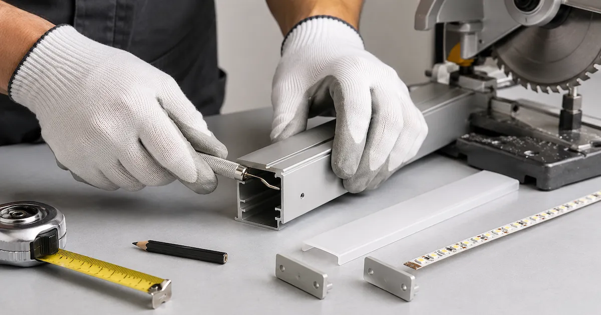
We once saw a cabinet project where the profile was cut accurately, but the strip was 18 mm too long to align with the cut mark. The installer folded the strip at the end, which created pressure under the cap and a visible bright hotspot. In another field example, metal burrs damaged cable insulation near the exit hole. That sort of hidden issue can become a safety problem.
From our manufacturing floor perspective, clean prep is not a small detail. It affects the final appearance, mechanical fit, and electrical reliability. Our Chief Engineer notes that rough cut edges often lead to diffuser cracking during press-fit assembly. So deburring is not optional.
| Preparation Step | What to Do | Risk if Skipped |
|---|---|---|
| Measure profile | Confirm final dimension | Wasted material |
| Mark strip cut point | Align with PCB cut marks | Strip damage |
| Cut aluminum cleanly | Use suitable blade | Crooked finish |
| Deburr edges | Smooth all cut points | Diffuser/end cap fit issues |
| Drill cable exit if needed | Protect wire path | Cable abrasion |
6. How do you mount the profile on different surfaces?
Mounting depends on the substrate. On wood or metal furniture, screws or clips are common. On gypsum or masonry, anchors may be required. In recessed work, the slot width and depth must fit the profile body and flange. Adhesive-only mounting can work in light-duty, low-heat, low-vibration cases, but it should not be your default choice for long-term projects.
But there is a catch. A straight profile installed on an uneven base will still look uneven. We often see installers rush this step in coves and long corridors, then the light line shows every alignment error once powered on. In a luxury hotel lobby, even a 2 mm deviation can become visible. In a retail display, poor alignment can distort product presentation.
In our project support experience, clips give better serviceability because the profile can be removed without damaging the substrate. Screws give stronger fixing for heavier or longer sections. Recessed plaster-in profiles need tighter coordination with ceiling or joinery teams so finishing work does not block the diffuser.
| Surface Type | Recommended Mounting | Notes |
|---|---|---|
| Wood panels | Screws or clips | Good for cabinets and shelves |
| Aluminum frames | Screws or compatible clips | Check galvanic contact areas |
| Gypsum board | Recessed slot or anchors | Coordinate with finishing team |
| Concrete/masonry | Anchors and screws | Pre-drill accurately |
| Glass/display structures | Special brackets or bonded fittings | Check load and safety |
7. How should you install the LED strip inside the profile?
Clean the channel before placing the strip. Dust, oil, and cutting residue weaken adhesion and reduce thermal contact. Dry-fit the strip, confirm polarity and cable exit direction, then peel and apply gradually without stretching the PCB. Press evenly along the strip so the adhesive backs the full length against the aluminum.
What is the real story? Many strip failures blamed on product quality are actually installation faults. We often see installers struggle with strips applied onto dirty channels or repositioned several times after the adhesive has already lost tack. In a display shelf project, a loose strip created local heating because only part of the PCB touched the profile. In a kitchen cabinet job, the strip crossed a screw head and lifted slightly, causing shadowing.
In our lab tests using thermal imaging, poor contact areas run hotter than properly bonded sections, which can lead to LED strip lights overheating in long-term use. That matters because excess heat shortens LED and adhesive life. Our technical team recommends applying strips at moderate room temperature and using thermal tape or mounting glue only when the strip specification calls for it.
A practical point: never force the strip around sharp internal corners inside the profile. Use connectors or short wire jumps where the design requires direction changes.
8. How do you wire, test, and close the system properly?
Complete all electrical connections before snapping in the diffuser. Use a multimeter to check input voltage, output voltage, polarity, dimming compatibility, and cable routing before closing the system. Soldered joints are usually more reliable than push connectors in tight channels, especially where vibration or repeated access is expected. If connectors are used, confirm they fit within the profile cavity without pressing on the diffuser.
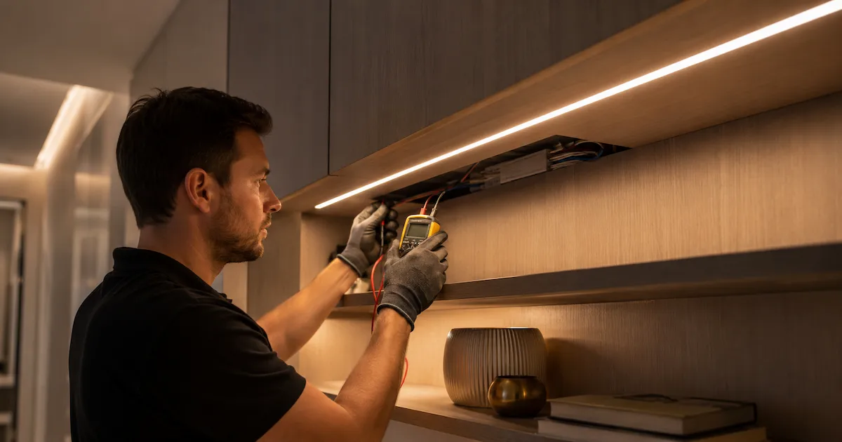
We once saw a site issue where the lighting looked fine on initial power-up, but the diffuser would not close fully because a connector sat too high above the strip. Another case involved dimming flicker caused by a driver mismatch, not by the profile itself. A third case came from reversed polarity on a short segment near an end cap, which delayed handover on a retail fit-out.
From our manufacturing floor perspective, final testing should include at least 15 to 30 minutes of operation before closure. That gives time to spot poor joints, thermal rise, or uneven brightness.
| Test Point | What to Verify | Acceptable Result |
|---|---|---|
| Power on | Full run lights evenly | No dark zones |
| Polarity | Positive and negative correct | No reverse wiring |
| Driver load | Within rated output | Stable operation |
| Dimming | Smooth control | No flicker or drop-out |
| Diffuser fit | Snaps or slides correctly | No pressure points |
9. What common installation mistakes cause callbacks?
Most callbacks come from a short list of avoidable errors. Wrong profile size. Poor heat dissipation. Under-rated driver. Single-end feeding on long runs. Misaligned recess. Dirty mounting surface. Damaged diffuser. Weak cable strain relief. These are basic points, but they still cause real cost.
Here is the quick truth. Small mistakes in linear lighting are highly visible. A recessed line that waves across a ceiling is noticed immediately. A color shift at the end of a shelf run makes merchandise look inconsistent. A failed adhesive inside custom furniture can require partial dismantling.
Common Myth: higher wattage always means better brightness. Reality: brightness depends on lumen output, optical losses through the diffuser, profile depth, and thermal performance. When we tested this against a standard 12V strip, a higher-watt strip in a shallow poor-quality profile actually produced a worse visual result than a lower-watt, higher-efficiency strip in a deeper aluminum channel.
For a practical visual explanation of common LED strip installation mistakes and how to avoid them, watch this neutral educational video before final testing and handover. Also, your internal link prompt has no internal links listed after it, so I can do that part once you send the link list.
| Common Problem | Likely Cause | Practical Fix |
|---|---|---|
| Uneven brightness | Voltage drop | Add power injection or use 24V |
| Visible LED dots | Shallow profile or clear cover | Use deeper profile with opal diffuser |
| Strip peeling off | Dirty channel or excess heat | Clean surface, improve thermal path |
| Flicker | Driver/control mismatch | Match driver and dimmer |
| Diffuser cracking | Rough cut or forced assembly | Deburr and recheck tolerance |
10. What final checks improve reliability and maintenance?
Before handover, inspect finish quality, light uniformity, thermal behavior, service access, and spare component records. Label drivers where practical. Keep a note of strip wattage, CCT, profile model, diffuser type, and driver reference. This helps future maintenance teams replace parts without guesswork.
We often see installers treat linear profile work as finished once the light turns on. But long-term reliability comes from final verification. In our lab tests using integrating spheres, optical consistency matters. On site, however, serviceability matters just as much. If a driver is hidden behind sealed millwork with no access, even a minor future replacement becomes expensive.
A simple handover checklist can save hours later. in one office project, recorded driver locations cut maintenance time sharply. And In a restaurant joinery installation, keeping spare diffusers avoided delays after accidental damage. Also in a residential premium fit-out, documenting color temperature prevented mismatched replacement sections months later.
| Final Check | Why It Matters | Action |
|---|---|---|
| Uniform light line | Confirms good install quality | Inspect powered run |
| Thermal check | Reduces early failures | Run system before handover |
| Driver accessibility | Simplifies maintenance | Confirm access panel |
| Product records | Helps exact replacement | Store model data |
| Spare parts review | Cuts downtime | Keep caps/diffusers if needed |
Conclusion
Installing LED linear profiles correctly is a mix of mechanical accuracy, electrical planning, and thermal discipline. Choose the right profile, plan the power layout, prepare cuts cleanly, mount straight, bond the strip properly, and test before final closure. That is what prevents visible defects, delays, and repeat visits. If you are unsure about profile size, driver loading, or voltage drop on a real project, send your drawings to our technical support team and we will help review the layout.
FAQ
Q1: What is the best profile depth to reduce LED dotting?
A deeper profile usually helps because the diffuser sits farther from the LEDs. COB strips can reduce dotting too, but profile depth, diffuser finish, and LED density all affect the final result.
Q2: Can I install LED strips in a profile without aluminum?
You can for some low-demand jobs, but it is not recommended for most professional installations. Aluminum helps with heat transfer, alignment, and physical protection.
Q3: Should I use 12V or 24V for linear profile lighting?
For longer runs, 24V is usually the better choice because it reduces current and helps limit voltage drop. For short cabinet or furniture sections, 12V can still work well.
Q4: Is adhesive alone enough to mount an LED linear profile?
Usually no for permanent work. Mechanical fixing with clips, screws, anchors, or recessed mounting is more reliable, especially on longer runs or warm environments.
Q5: How long should I test the system before handover?
A practical minimum is 15 to 30 minutes under normal operation. For larger jobs, longer testing is better so you can catch thermal rise, flicker, or unstable connections.
