
Installing Channel Letters on Interior Drywall means mounting illuminated letter signs to gypsum board using the right support, wiring path, LED driver, and service plan. The goal is simple: a clean sign face, stable letters, safe low-voltage wiring, and no drywall cracking after handover.
1. What Makes Interior Drywall Different for Channel Letters?
Interior drywall is a finish surface, not a structural sign frame. That is the main point many projects miss. A channel letter set may weigh only a few kilograms, but the load is spread through small fastener points. If those points land on hollow gypsum with weak anchors, the letters can sag or rotate over time.
We often see installers struggle with three drywall realities: uneven backing, unknown stud spacing, and fragile painted finishes. In a retail store, a sign behind the cashier may be touched during cleaning every day. In a hotel lobby, clients view the letters from close distance, so even a 2 mm gap looks like poor workmanship.
Drywall load behavior
Drywall handles compression better than pull-out force. Channel letters create pull-out force at the mounting holes, mainly if the letters stand off the wall. Raceway-mounted signs reduce some layout work, but the raceway still needs solid fixing.
| Drywall Condition | Installation Risk | Recommended Action |
|---|---|---|
| Standard 12.5 mm gypsum board | Anchor pull-out under vibration | Use toggle anchors or hit studs |
| Double-layer fire-rated board | Hidden assembly rules | Confirm drilling limits with site manager |
| Feature wall over furring strips | Variable cavity depth | Measure cavity before anchor choice |
| Painted skim coat | Chipping around holes | Tape, pilot drill, and cut clean openings |
| Moisture-prone interior area | Corrosion and board softening | Use coated hardware and sealed penetrations |
Beyond mechanical behavior, drywall can also reveal finish tolerances: small undulations or drywall joints close to mounting points create visible shadow lines on halo-lit letters. Plan for filler or local backing where necessary, and be ready to apply small cosmetic repairs after installation to maintain a pristine finish.
2. How Should You Survey the Wall Before Drilling?
A good wall survey saves time and protects margin. Before drilling, check the wall type, stud locations, cavity depth, power source, viewing height, and local site rules.
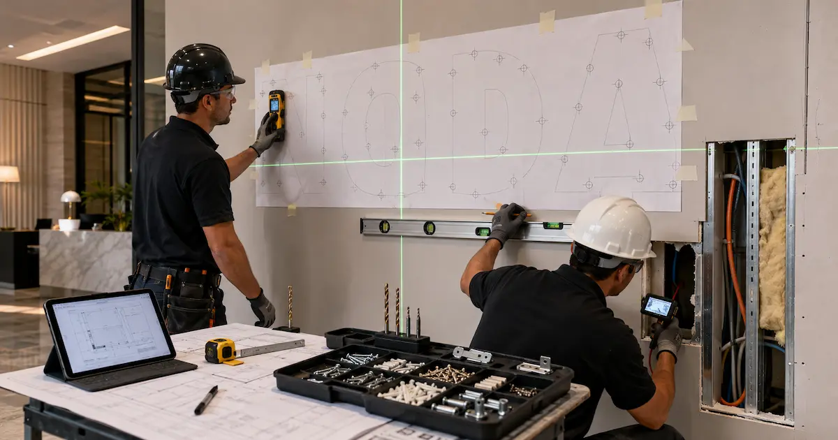
Start with a stud finder, magnet, inspection camera if needed, and a low-voltage detector. Mark studs with removable tape and compare those marks with the channel letter template. If mounting holes do not align with studs, use a backing plate, toggle anchors, or a raceway.
Document your survey with photos. Share them with the project manager before drilling.
Wall survey checklist
| Survey Item | Tool or Method | Why It Matters |
|---|---|---|
| Stud location | Stud finder and magnet | Gives stronger fixing points |
| Cavity depth | Test hole or inspection camera | Prevents anchors hitting blockwork |
| Power route | Electrical drawing and detector | Reduces risk of cable damage |
| Wall flatness | 1.2 m level | Prevents letter rocking and shadow gaps |
| Paint finish | Visual check and tape test | Avoids flaking during template removal |
| Fire rating | Site document review | Protects compliance and liability |
Add an inventory note to the survey: list nearby HVAC runs, plumbing, and low-voltage raceways. This reduces surprises when pulling cables and speeds up the decision on whether to use surface raceways or concealed wiring. Also confirm cleaning schedules or public access times so installers can plan undisturbed work windows.
3. Which Mounting Method Works Best: Stud Fixing, Toggle Anchors, or Raceway?
The best mounting method depends on weight, wall build-up, service access, and visual requirements. Stud fixing gives the strongest support, but studs rarely line up perfectly with every letter. Toggle anchors work well for hollow drywall if the load is moderate. A raceway simplifies wiring and spreads the mounting load, but it changes the appearance and must still support the lighting and wiring requirements for illuminated signage.
Common Myth: drywall anchors are all the same if the weight rating looks high. Reality: the rating often comes from lab pull tests on clean board. Real walls have paint layers, old holes, impact damage, and uneven cavities. The anchor style must match the board thickness and load direction.
| Mounting Method Vs. Criteria | Stud Fixing | Toggle Anchors | Raceway Mounting |
|---|---|---|---|
| Strength | High | Medium to high | High if fixed well |
| Visual cleanliness | Very clean | Very clean | Raceway visible |
| Wiring ease | Medium | Medium | Easy |
| Service access | Medium | Medium | High |
| Best use case | Heavy letters or standoffs | Light to medium letters | Multi-letter sets with tight schedule |
| Main risk | Misaligned studs | Board damage | Client dislikes visible box |
The following neutral Science Channel video shows how channel signs are manufactured and assembled, helping installers understand the letter structure they must securely mount, wire, and service on an interior drywall surface.
Pro Tip from the VST Technical Team: “For drywall, treat the sign as a system, not only as letters. Fixing, wiring, driver heat, and service access all affect the real life of the installation.”
When deciding, consider the environment: high-traffic areas or places where cleaning staff might lean on letters favor backing or stud-fix solutions. For temporary installations or leased spaces, raceways may be preferred for faster removal. Always include an installation mock-up in the planning stage for projects where aesthetics are critical.
4. How Do You Choose Anchors and Hardware for Drywall Channel Letters?
Anchor choice affects safety and appearance, so contractors should review the sign weight, dimensions, mounting points, and other product details before selecting drywall hardware. For interior channel letters, common options include snap toggles, butterfly toggles, hollow-wall anchors, plastic expansion plugs, and direct screws into studs. For professional work, plastic plugs in hollow drywall should be avoided for illuminated letters unless they carry only a light template or trim part.
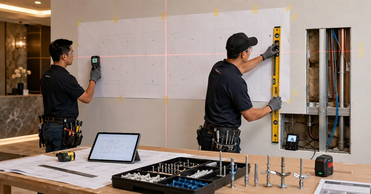
Use corrosion-resistant screws even indoors. If the letters use aluminum returns, stainless screws reduce staining around holes. For painted walls, use nylon washers or rubber pads where needed to prevent metal-to-paint rubbing.
Anchor selection table
| Anchor Type | Typical Use | Strength Level | Notes for Drywall |
|---|---|---|---|
| Snap toggle | Medium letters, hollow cavity | High | Good pull-out resistance |
| Butterfly toggle | Light to medium letters | Medium | Needs enough cavity depth |
| Metal hollow-wall anchor | Light letters | Medium | Can crush weak board if over-tightened |
| Screw into stud | Heavy letters | High | Best if layout aligns |
| Plastic plug | Very light trim only | Low | Poor choice for load-bearing letters |
Do not over-tighten. Tighten until firm, then stop.
Include torque guidance in your job notes: some toggles recommend a nearly hand-tight finish, while stud screws may be gradually tightened with a torque-limited driver to avoid twisting the letter return. If working with a painted or delicate finish, protect the wall with an adhesive-backed thin foam pad behind the letter return to spread point loads and prevent paint scuffs during final tightening.
5. How Should LED Power and Wiring Be Planned Behind Drywall?
LED channel letters usually run on low-voltage DC, often 12V or 24V. The driver connects to mains power and feeds the modules inside each letter, while proper LED light-strip wiring ensures correct polarity, cable sizing, protected connections, and reliable power distribution. The driver location must allow cooling, access, and compliance with local electrical rules, and project teams should resolve any unresolved technical questions through a reliable LED lights FAQ before the installation begins.
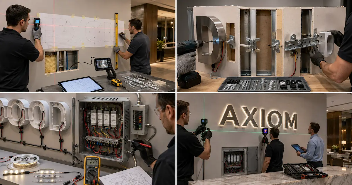
For interior drywall, wiring can be routed through the cavity, through a raceway, or from a nearby cabinet, ceiling void, or service panel. If the wall is fire-rated, do not make penetrations without approval and appropriate fire stopping, and ensure the sign’s electrical design follows the applicable National Electrical Code requirements.
Size the driver with headroom and complete the required LED driver load calculation before deciding how many channel letters each power supply will feed. A common target is to load the driver at 80% or less of rated capacity to reduce heat stress and improve reliability.
| Power Option Vs. Factor | 12V LED Modules | 24V LED Modules |
|---|---|---|
| Voltage drop resistance | Lower | Higher |
| Short small signs | Good | Good |
| Longer runs | More feed points needed | Fewer feed points needed |
| Driver availability | Very common | Very common |
| Wire size pressure | Higher current | Lower current |
| Service preference | Easy replacement | Better for larger sets |
Label every driver and wire run clearly before concealment. Include the following on a small laminated installation card placed behind accessible panels: driver type and model, input and output voltage, fuse rating, last bench test date, and contact for spare parts. This simple habit reduces truck rolls when future maintenance is required. Also plan for knockouts or conduit stubs when installing drivers to make future rework straightforward.
6. How Do You Lay Out and Align Channel Letters Accurately?
Alignment is where the client judges your work in seconds. Use a full-size paper template, laser level, centerline marks, and a two-person verification before drilling.
Tape the template to the wall with low-tack tape. Check viewing height from the actual customer path, not only from a ladder. Use small spacers or standoff adjustments to maintain a consistent plane, especially for halo-lit letters where light wash reveals wall defects.
Layout process
| Step | Action | Checkpoint |
|---|---|---|
| 1 | Mark horizontal centerline | Confirm with laser level |
| 2 | Mark vertical centerline | Match brand drawing |
| 3 | Tape template | Avoid stretching paper |
| 4 | Verify from floor | Check real viewing angle |
| 5 | Drill pilot holes | Use correct bit size |
| 6 | Test fit letters | Confirm spacing before wiring |
Take photos before and after drilling for QA and client approval.
Add a dry-run step: loosely fasten a single letter or a test bracket and view it from key sightlines before final torque. This quick check avoids costly re-drilling and ensures the plane of letters looks uniform against common camera angles used in marketing photography or brand inspections.
7. What Safety and Code Points Apply to Interior LED Channel Letters?
Interior signs still carry electrical and fire safety responsibilities. Low voltage does not remove the need for correct drivers, cable protection, strain relief, maintenance access, and appropriate electrical safety in construction practices. The driver must match input voltage, output voltage, load, dimming method if used, and local certification needs; contractors can also review the company’s lighting product and manufacturing background when confirming technical capability and quality-control support.
Use cable grommets where wires pass through metal returns, and consult a recognized wire and cable application guide when selecting conductors for the installation environment. Add strain relief so wire movement does not pull solder joints. Keep mains and low-voltage wiring separated according to local rules. If dimming is required, match the driver and control method, such as 0-10V, TRIAC where suitable, DALI, or PWM.
| Safety Item | Good Practice | Risk If Ignored |
|---|---|---|
| Driver certification | Match project region | Inspection failure |
| Heat space | Allow airflow around driver | Short driver life |
| Wire protection | Use grommets and bushings | Insulation damage |
| Load calculation | Keep driver load near 80% | Overheating and flicker |
| Access panel | Leave reachable service point | Costly wall opening later |
Record conformity checks and keep them with the project file: driver datasheets, certificate numbers, and installation photos. When working in commercial buildings, coordinate with the building facilities manager to ensure your installation doesn’t interfere with emergency lighting or life-safety systems.
8. How Can You Control Brightness, Color, and Heat on Drywall Signs?
Brightness must suit the room. Use LED modules with known lumen data, color temperature, and beam angle. For acrylic-faced letters, module spacing controls hot spots. For halo-lit letters, wall distance and surface reflectance shape the glow.
Common Myth: higher wattage always means better brightness. Reality: brightness depends on lumen efficiency, optical layout, face material, letter depth, and heat control, as explained in the U.S. Department of Energy’s overview of LED basics. More watts can create more heat, reducing LED life.
| Parameter | Typical Interior Recommendation | Why It Matters |
|---|---|---|
| Color temperature | 3000K, 4000K, 6500K by brand need | Keeps brand tone consistent |
| CRI | 80+ for most signs, 90+ for premium interiors | Improves color perception |
| Driver load | 70–80% of rating | Lowers heat stress |
| Module spacing | Based on letter depth and face material | Reduces hot spots |
| Burn-in test | 2–4 hours before installation | Catches early failures |
For spaces with mixed lighting (retail, galleries, restaurants), match the channel letter color temperature to the ambient lighting plan and the brand guidelines. If the sign will be photographed for promotion, test and photograph at the expected time of day and under the store lighting to avoid surprises. Include thermal monitoring on prototypes for large runs to identify hot spots and change module density or add small vents in raceways if necessary.
9. What Installation Workflow Reduces Callbacks?
A repeatable workflow protects your team from missed steps. It also gives distributors and project managers a clean way to train installers. The workflow should cover receiving inspection, bench testing, layout, drilling, wiring, mounting, power testing, cleanup, and handover photos.
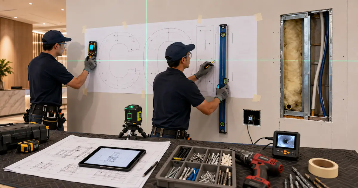
Start by checking the carton contents against the sign drawing. Bench test the sign before it touches the wall. For larger sets, label each letter on the rear side to match the template.
Step-by-step installation checklist
| Stage | Action | Pass/Fail Check |
|---|---|---|
| Receiving | Inspect letters and driver | No damage, correct voltage |
| Bench test | Power each letter safely | All modules light evenly |
| Wall survey | Mark studs and obstacles | No conflict with power route |
| Template | Align and tape | Client or supervisor approval |
| Drilling | Use pilot holes | No wall cracking |
| Wiring | Pull and label cables | Correct polarity |
| Mounting | Tighten evenly | No wobble or gaps |
| Testing | Run for 30–60 minutes | No flicker or hot smell |
| Handover | Provide photos and notes | Service route documented |
Include an on-site sign-off sheet for the client or facilities manager that documents the driver serial numbers, power feeds used, and any deviations from the original plan. This formalizes acceptance and reduces disputes after handover.
10. How Do You Troubleshoot Problems After Installation?
Post-install issues usually fall into mechanical movement, uneven light, flicker, and access problems. Handle troubleshooting in a structured order: measure voltage, check connections, confirm driver load, and follow a professional process for fixing flickering LED lighting before replacing modules or power supplies.
Common failure modes and fixes
| Symptom | Likely Cause | Practical Fix |
|---|---|---|
| Letter feels loose | Anchor crushed drywall | Replace with toggle or add backing plate |
| One letter is dim | Voltage drop or bad module | Measure voltage, inspect modules |
| All letters flicker | Driver overload or dimmer mismatch | Reduce load or change driver type |
| Hot smell near driver | Poor airflow or overload | Relocate driver, lower load |
| Uneven halo light | Wall texture or standoff variation | Adjust standoffs, repaint background |
| Buzzing sound | Driver or dimmer conflict | Match control protocol |
Keep spare modules, matching connectors, and driver data on file for fast service.
When called back to site, follow a documented triage process: ask for recent photos, confirm ambient conditions (temperature, other loads on same circuit), and if possible, request a short video showing the issue while you talk to the on-site contact. This reduces unnecessary site visits and improves first-visit resolution rates.
Conclusion
Installing channel letters on interior drywall works best when you treat the wall, fixing hardware, LED system, and service plan as one package. Survey the wall, choose anchors based on real load behavior, plan wiring and driver location, control heat, and test thoroughly before handover. Preparation prevents callbacks and protects reputation. If you are unsure about anchor load, voltage drop, driver placement, or service access for a specific job, contact our engineering team and send the project drawings for manual review.
FAQ
Q1: What is the best anchor for installing channel letters on interior drywall?
Snap toggles or quality toggle bolts are usually best for hollow drywall. For heavy letters, fixing into studs or using a concealed backing plate is safer. If you are in doubt, test one anchor in a concealed area and record pull-out performance before committing to the full install.
Q2: Can LED channel letters be mounted directly to drywall without a raceway?
Yes, if the wall can carry the load and the wiring route is planned. Direct mounting gives a cleaner appearance but requires accurate templates, proper anchors, and accessible driver placement. Consider the long-term maintenance plan: direct mounts sometimes make driver access harder, so plan removable service panels or accessible ceiling routes where possible.
Q3: Should I use 12V or 24V LEDs for interior channel letters?
Both work. For small signs, 12V is common. For longer wire runs or larger letter sets, 24V can reduce voltage drop and help keep brightness consistent. Balance the decision with driver availability on-site and spare inventory — 24V systems generally need fewer feed points but may require slightly different connectors.
Q4: Where should the LED driver be placed for drywall-mounted letters?
Place the driver in a ventilated, reachable location such as a ceiling void, cabinet, service panel, or raceway. Avoid sealing it inside the wall where heat and service access become problems. If the driver must be concealed, provide a clearly labeled access panel and include ventilation gaps to prevent thermal buildup.
Q5: Why do channel letters flicker after installation?
Common causes include driver overload, poor connections, reversed polarity, voltage drop, or a dimmer that does not match the driver. Measure voltage and check compatibility before replacing parts. Also verify that the control protocol (0-10V, TRIAC, PWM, etc.) is supported and configured correctly on both driver and control device.
